Decoding Milwaukee Packout Hole Patterns and Tolerances for Flawless Fit
Introduction to Secure Tool Storage
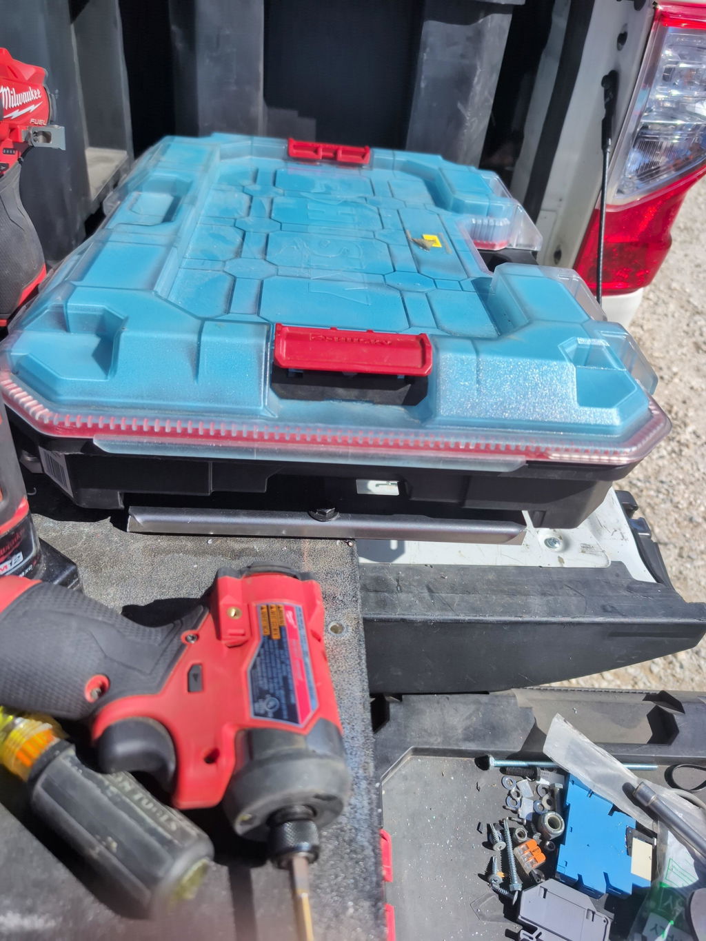
Secure tool storage isn’t just about neatness; it’s about speed, safety, and protecting your investment when the truck hits washboard roads or the gang box gets moved by a forklift. For tradespeople who rely on Milwaukee’s modular ecosystem, the difference between a rock-solid setup and a rattling liability often comes down to how faithfully your Packout mounting hole patterns are executed.
The Packout interface uses a specific geometry of locking cleats, latch windows, and keep-out zones. When those features are replicated with precision—whether on a wall plate, cart top, service-van bulkhead, or trailer rack—cases lock in with a positive click and release cleanly. When they’re off by even a small margin, you’ll see binding, premature wear, or boxes walking loose under vibration. That’s why custom fabrication accuracy and a clear dimensional tolerance guide are essential for secure tool organization.
Fabricators face two big variables: the cutting process and the finish. Laser, plasma, and waterjet each produce different kerf widths and edge tapers that affect slot fit. Then the finish—powder coat often adds 2–4 mils per side per coat—tightens clearances you thought were generous on raw steel. Accounting for both up front prevents rework and field failures.
Fabrication design tips to get a flawless fit:
Prioritize center-to-center accuracy. Even if slot widths are generous, cumulative error in spacing can misalign latch engagement points.
Radius internal corners. Sharp inside corners concentrate stress and can chip powder coat, leading to corrosion and loose fit over time.
Add clearance for fasteners. Countersunk screws and rivnuts near the interface can interfere with Packout feet; design low-profile hardware paths or recesses.
Control slot width by process. If you cut with plasma, oversize the CAD feature to net the intended opening after kerf; with fiber laser, you can hold tighter tolerances and reduce post-processing.
Model the finish. Offset cut paths or scale features so final coated dimensions match the functional target.
Test with a sacrificial coupon. A small test plate validates latch engagement, rattle, and release force before you commit to a full run.
Boco Custom solves these variables with heavy-duty, low-profile plates that arrive powder-coated and ready to mount, with same-day shipping and local pickup available. If you prefer to build in-house, our instant-download DXF files embed true-to-spec Packout mounting hole patterns and practical tolerance allowances, so your parts fit on the first try and your tool mounting solutions stay locked in under real jobsite abuse.
Why Precision Mounting Matters
Getting the interface right between the Packout cleats and your plate is the difference between a crisp, one-handed lock-in and a module that chatters, wears prematurely, or pops loose under vibration. Packout mounting hole patterns aren’t just dots on a drawing; they define latch engagement, load paths, and repeatability across your entire storage ecosystem.
On the road, small errors compound. A van bulkhead carrying a 60 lb stack may see thousands of vibration cycles per mile. If the slot width is undersized by a fraction or the latch window is off-center, the feet ride the edges instead of fully seating. That translates into rattle, paint wear, and lost confidence in your tool mounting solutions.
Precision also drives interchangeability. When every mounting plate follows the same datum scheme and tolerances, you can move modules from the wall to a cart to a drawer without rework. Fabricators building jigs, racks, or drawers from instant-download DXF files rely on custom fabrication accuracy so every part produced on different machines still fits.
Where tight tolerances matter most:
Slot width and length for the rear feet to enter and seat fully
Front latch window position relative to the rear slots
Depth and relief at foot contact points to avoid bottoming
Fastener hole size and pattern that anchors the plate without distortion
Edge radii/chamfers that guide feet and reduce coating scuff
Coating and process choices affect fit. Powder coat adds measurable thickness to contact faces; plan clearance to maintain smooth engagement after finishing. Laser kerf varies by material and machine; apply kerf compensation in your CAM so a 10.00 mm slot isn’t delivered as 9.70 mm. Waterjet and CNC routing introduce different edge taper and corner radii—account for these in your dimensional tolerance guide.
Concrete example: If your DXF calls for a 20.00 mm latch window and your shop consistently cuts 0.15 mm undersize and later adds 0.08 mm of coating per side, you’ve effectively removed nearly half a millimeter of clearance. That can prevent full latch throw. Design in nominal clearances (for example, 0.3–0.6 mm per side on sliding features) and document them.
Practical fabrication design tips:
Establish a single datum corner and locate all Packout features from it to reduce stack-up
Use test coupons to validate slot clearance before running production
Specify countersinks/counterbores to match your fasteners to keep heads flush and modules flat
Deburr and break edges in contact zones to prevent galling on coated or stainless parts
Verify flatness after welding or forming; shim or stress-relieve if needed to keep modules seated
Ultimately, precise Packout mounting hole patterns are about dependable, secure tool organization that survives the jobsite. Tolerance-aware drawings and vetted DXF files help you deliver plates that lock solidly, swap cleanly, and stand up to daily use.
Common Tool Storage Hole Patterns
Across the industry, tool systems use repeatable patterns to make mounting fast, accurate, and interchangeable. Knowing the common grids and slot standards helps you mix Packout mounting hole patterns with other tool mounting solutions and design brackets or plates that install without fiddling.
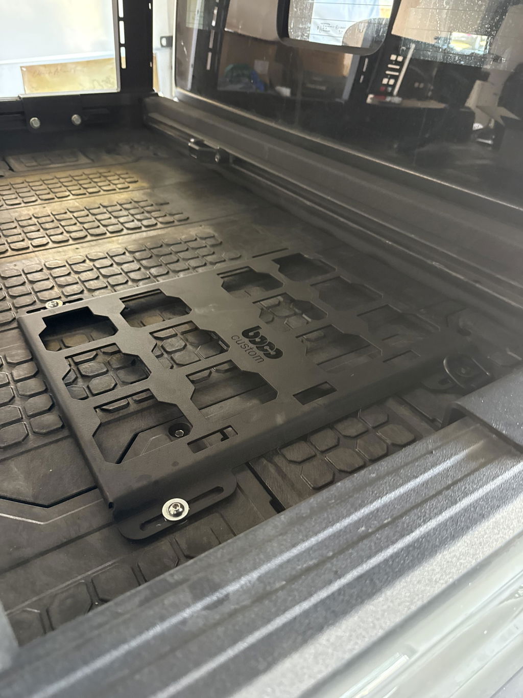
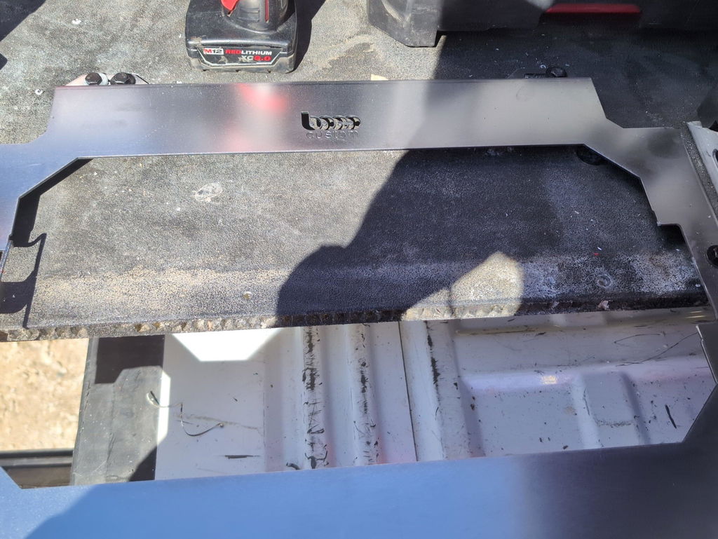
Milwaukee Packout interface
Illustration for Decoding Milwaukee Packout Hole Patterns and Tolerances for Flawless Fit
The Packout base locks into shaped windows, not simple “round holes.” These windows need crisp corners, correct lead-ins, and consistent slot width to engage the cleats.
For fabricated steel or aluminum plates, hold the latch windows and hooks to tight working tolerances—aim for ±0.25–0.50 mm (±0.010–0.020 in) on critical features.
Account for finish: powder coat typically adds 0.075–0.15 mm (0.003–0.006 in) per side. Add clearance accordingly or mask latch windows before coating.
Use oblong mounting slots in the plate-to-surface fastener pattern to allow a few millimeters of adjustability during install.
Other widely used patterns you’ll encounter
Pegboard: 1" on-center grid. Hole diameters commonly 1/4" (heavy-duty) or 1/8" (light-duty). Useful for quick accessory plates that also accept standard hooks.
Unistrut/Strut channel (P1000): 1-5/8" channel with elongated slots typically 1-1/8" x 9/16" at 2" centers. Excellent backbone for modular van upfits and shop racks.
T-slot aluminum (extrusion): 10-series (1" / 25.4 mm module) and 15-series (1.5" / 38.1 mm). Slot widths commonly 6–8 mm; fasteners are M6/M8 or 1/4-20/5/16-18 depending on series.
Airline L-Track: Countersunk mounting holes often spaced 4" on-center (varies by manufacturer). Use 82° (imperial) or 90° (metric) countersinks to keep fasteners flush for slide-in fittings.
Square bolt grids: 25 mm, 32 mm, or 50 mm on-center M6/M8/M10 patterns are common on custom panels and machine bases to maximize accessory compatibility.
Dimensional tolerance guide and fabrication design tips
Choose the fastener system first, then match countersink angle: 82° for flat-head inch hardware, 90° for metric.
Maintain edge distance ≥ 2x material thickness (or ≥ 1.5x for aluminum with backing) to avoid pull-out.
When using rivnuts, follow the manufacturer’s drill size; as a reference, M6 rivnuts commonly require ~9.0 mm holes.
Validate critical Packout latch features with a printed template or a verified DXF before cutting production parts to ensure secure tool organization without trial-and-error.
Accurate, well-dimensioned templates and DXF files remove guesswork, improve fit, and keep your system low-profile and secure.
Understanding Manufacturing Tolerances
When you’re designing to Packout mounting hole patterns, “nominal” dimensions are only a starting point. Plastic components, molded ribs, and small tooling revisions can shift real-world fit by a few tenths of a millimeter. The goal is a controlled clearance fit that engages securely without binding, even after coating and heavy use.
Think in terms of tolerance stack-up. A hole or slot that’s 0.15 mm tight may still assemble once, but replicate that error across a grid and you’ll be fighting every install. For vehicle-mounted tool mounting solutions, vibration amplifies any misfit, so predictable engagement and repeatable location matter more than hitting a single perfect number.
Process capability drives your dimensional results. Laser, waterjet, and CNC each have different kerf, taper, and heat input. Powder coating adds thickness and edge build that reduce clearances. If you design at exact CAD nominal and ignore these, you’ll cut a batch that fits in raw steel and binds after finishing.
Use a practical dimensional tolerance guide like this:
Slot/feature width: oversize by +0.15 to +0.30 mm (+0.006 to +0.012 in) relative to the measured Packout engagement feature to ensure smooth lock-in after coating and deburr.
Center-to-center pitch: hold ±0.20 mm (±0.008 in) or better. Cap cumulative error under 0.50 mm (0.020 in) across three or more features.
Edge radii: use ≥3.0 mm (1/8 in) internal corner radii on slots to reduce stress and avoid crack initiation.
Flatness: keep plates within 0.5 mm per 300 mm (0.020 in per foot) to avoid rocking and partial engagement.
Coating allowance: assume 0.05–0.10 mm (2–4 mil) per side for powder coat; mask or open up critical edges accordingly.
Fastener holes: provide +0.20 to +0.30 mm clearance for M6 / 1/4-20 hardware and specify countersink/counterbore tolerances separately.
Fabrication design tips that prevent headaches:
Add 30–45° lead-in chamfers or small ramps on entry edges to guide the Packout latch.
Normalize or flatten laser-cut plate before coating; thin sheet can potato-chip during cutting.
Compensate kerf in CAM, not by “eyeballing” in CAD; kerf drift with material thickness can be 0.05–0.20 mm.
Prototype in scrap and build a go/no-go gauge from a real Packout base to validate your pattern before production.
Boco Custom plates and downloadable DXF files are built around proven Packout mounting hole patterns and account for real-world process variables. Whether you fabricate in-house or need ready-to-install, low-profile plates, dialing in these tolerances is the key to secure tool organization and flawless fit.
Measuring and Verifying Dimensions
Start by establishing reliable datums. Square the plate and pick a consistent 0,0 corner. Dimension all features of the Packout mounting hole patterns from that corner (and one orthogonal edge) rather than chaining dimensions from hole to hole. This prevents cumulative error and simplifies inspection.
Measure critical features with the right tools:
Digital calipers for edge-to-edge and edge-to-center dimensions.
Pin gauges (or drill bits used as pins) to verify hole diameters and slots.
A machinist square and straightedge to check flatness and orthogonality.
A scale-verified print (1:1 test plot) to overlay on the workpiece for a quick sanity check.
When reverse-engineering or validating a DXF, confirm these points on at least three spots across the plate:
Center-to-center spacing of latch openings and alignment holes, holding ±0.25 mm (±0.010 in) positional tolerance relative to the datums.
Actual opening width and length. Provide +0.20 to +0.40 mm clearance per side over the nominal feature so the latches engage smoothly without rattle.
Corner radii of slots/rectangles. Match them to your cutting process kerf (e.g., 0.5–1.0 mm internal fillet for laser) to avoid stress risers and misfit.
Account for process variation and finish:
Laser kerf: ~0.10–0.20 mm; waterjet: ~0.10–0.30 mm; CNC plasma: ~0.80–1.50 mm. Offset geometry in CAD/CAM to land at net size.
Powder coat adds 0.05–0.10 mm per side (2–4 mils). Increase critical openings by 0.10–0.20 mm beyond bare-metal targets when coating.
Material thickness affects latch engagement. Validate with a real module at the intended thickness. If using ≥3.2 mm (1/8 in), chamfer entry edges of latch windows to aid secure lock-in.
Practical verification steps for custom fabrication accuracy:
Cut a small test coupon that includes one full latch window and alignment feature. Fit-test before running the full sheet.
Use go/no-go pins for hole checks. For M8 clearance holes, for example, accept 8.5 mm go and reject 8.8 mm.
Inspect symmetry. Measure diagonals across mounting features; they should match within 0.25 mm.
Avoid sharp transitions. Inside corners below 1.0 mm radius may trap coating and shrink clearances.
CAD and DXF handling tips:
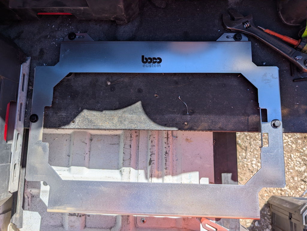
Illustration for Decoding Milwaukee Packout Hole Patterns and Tolerances for Flawless Fit
Confirm unit scale (mm vs in) on import. Measure a known feature in CAD before cutting.
Suppress duplicate/stacked paths to prevent overburn.
Dimension features to datums in the model; avoid “floating” sketch references.
These fabrication design tips form a dimensional tolerance guide that leads to secure tool organization. If you prefer ready-to-cut accuracy, Boco Custom’s DXF files for common tool mounting solutions implement verified offsets and clearances for consistent, repeatable fits.
Fabrication Tips for Perfect Fit
Before you cut metal, lock down the reference. Packout mounting hole patterns are forgiving in function but unforgiving in alignment. Start with verified geometry to avoid stack-ups that make latches bind or trays rock under load.
Use a master pattern
Source a vetted DXF rather than tracing by hand. Confirm the file’s units (mm vs in) on import.
Print the DXF 1:1 and overlay it on an OEM Packout base to validate 3–5 critical features.
If you must measure, pick three datums (primary face, long edge, short edge) and dimension all features back to them—avoid chain dimensions.
Control tolerances with intent
Set a general profile tolerance for plate features (±0.25 mm/±0.010 in) and a tighter true position for engagement holes/slots (≤0.50 mm/0.020 in to datums).
Oversize clearance holes based on fastener: M6 = 6.6–7.0 mm; 1/4-20 = 7.1–7.5 mm. Slot for ±3 mm adjustability when mounting to vehicles.
Keep minimum edge distance at ≥1.5× material thickness for holes; ≥2× for slots.
Account for process variables
Laser kerf: ~0.1–0.2 mm; waterjet: ~0.3–0.8 mm; plasma: ~1.0–1.5 mm. Compensate in CAM and use small lead-ins away from tight pockets.
Use micro-tabs to control heat movement; post-cut, deburr both sides to remove recast and burrs that can interfere with latch engagement.
Design for coating and finish
Powder coat adds ~0.05–0.10 mm per side. Enlarge critical engagement features by 0.15–0.30 mm or mask those regions.
Break edges to a 0.5–1.0 mm radius. Add 3 mm internal radii on corners of slots to reduce crack initiation.
Maintain stiffness and flatness
For heavy-duty tool mounting solutions, 12–10 ga steel (2.5–3.5 mm) or 3–4.8 mm aluminum resists vibration without bulk.
Use flanges, ribs, or return bends instead of extra thickness to keep a low profile and maintain flatness across long spans.
Verify fit early
3D-print a gauge of the engagement features before committing to metal.
Perform a go/no-go test with an actual Packout base on the raw cut, then again after coating.
Plan fasteners and clearance
Rivnuts or weld nuts keep the surface flush; countersink where needed but check material thickness for head seating.
Keep the latch sweep path clear; maintain a 2–3 mm gap around latch pockets for reliable operation.
If you prefer to skip reverse-engineering, start from a proven dimensional tolerance guide and verified DXF tailored to Packout mounting hole patterns to maximize custom fabrication accuracy and ensure secure tool organization.
Ensuring Long-Term Mounting Security
Long-term security starts with precision. If Packout mounting hole patterns are even slightly off, latch engagement can be inconsistent, loads can shift, and wear accelerates. Build accuracy into the design by controlling cumulative error: locate all critical features from a single datum, cut in one setup when possible, and avoid hand-drilled “match fits.” Typical laser/waterjet processes can hold tight positional tolerances; leverage that capability and verify center-to-center spacing with a template before committing to a production run.
Account for finishing. Powder coat adds thickness that can tighten fits and reduce latch clearance. Mask critical interfaces or add a small allowance to slot geometry to maintain smooth engagement after coating. Deburr and break edges to prevent premature abrasion of the Packout feet and to reduce stress risers around fasteners.
Choose hardware that matches the duty cycle. For vehicle and jobsite vibration, use mechanical retention: nyloc or all-metal locknuts, serrated flange nuts, or medium-strength threadlocker on clean threads. Pair bolts with large OD washers or backing plates to spread load on thin substrates. In mixed-material builds, isolate dissimilar metals with nylon washers or paint to mitigate galvanic corrosion.
Design for the real load path, not just static weight. Dynamic forces in a service van can exceed static loads several times. Keep heavy items low and close to structure, minimize cantilevers, and tie into ribs or studs. Example: mounting to van sheet metal—use rivet nuts with a continuous backing plate behind corrugations rather than sheet-metal screws alone. In a shop, align your hole pattern to hit studs; use lag screws and fender washers rather than anchors in drywall.
Illustration for Decoding Milwaukee Packout Hole Patterns and Tolerances for Flawless Fit
Plan for inspection. Re-torque fasteners after the first week of use, then set quarterly checks. Look for witness marks at latch interfaces, elongated holes, or powder-coat cracking—early signs that tolerances are drifting under load.
For builders, instant-download DXF files help maintain custom fabrication accuracy. A dimensional tolerance guide embedded in your CAD pack reduces guesswork and rework. If you’d rather skip prototyping, Boco Custom’s heavy-duty, low-profile, powder-coated plates are engineered around precise Packout mounting hole patterns and ship same day, delivering secure tool organization without the trial-and-error.
Fabrication design tips to remember:
Keep critical features on one datum; avoid stacking tolerances.
Allow for coating thickness at latch and slot interfaces.
Use vibration-resistant hardware and proper backing.
Validate fit with a printed template before cutting metal.
Impact of Accuracy on Efficiency
Precision in Packout mounting hole patterns translates directly into faster setups, fewer adjustments, and reliable repeatability across job sites. When every cleat seats cleanly the first time, you’re not burning minutes widening slots, re-drilling, or shimming mounts—your tools lock in, stay secure, and move with you.
Small deviations compound. A hole-to-hole pitch error of just 0.2–0.3 mm across a multi-row layout can stack into a millimeter or more of misalignment by the outer holes. That’s enough to cause hard engagement, rattle, or a latch that won’t fully lock. Over a day, those micro-fixes add up to lost productivity and inconsistent tool mounting solutions from one vehicle or wall panel to the next.
Aim for tight, achievable tolerances and a robust datum strategy:
Establish primary and secondary datums at the center of the pattern to minimize cumulative error at the edges.
Target true position within ±0.25 mm (±0.010 in) for hole centers on critical features; relax non-critical mounting holes to save cost.
Control parallelism and perpendicularity so slots align with Packout cleats, reducing binding during engagement.
Maintain plate flatness; minor warp forces parts to “spring” during install and can pop locks under vibration.
Account for process variables before you cut:
Kerf and heat input: Laser offers tighter kerf and lower heat distortion than plasma. If plasma cutting, compensate for larger kerf and potential taper; finish critical edges after cutting.
Powder coat build: Typical 2–4 mil (0.05–0.10 mm) per side reduces slot width by 0.10–0.20 mm overall. Oversize critical openings accordingly or mask and post-finish to preserve fit.
Material movement: Long slots can close slightly after cutting. Use stress-relieved plate and sequence cuts to minimize distortion.
Fabrication design tips that boost efficiency:
Add controlled clearance where it helps (elongated attachment holes for mounting to uneven substrates), but keep Packout engagement features tight for secure tool organization.
Deburr and break edges to protect case latches and prevent paint chipping that can change fit over time.
Validate with a printed 1:1 template or a quick MDF prototype before committing to metal.
Use verified DXF files to eliminate redraw errors and maintain consistent dimensional tolerance guide standards across batches.
Boco Custom’s heavy-duty, low-profile plates and instant-download DXF files are engineered around precise Packout mounting hole patterns, reducing rework and ensuring repeatable, secure installs—whether you’re fabricating in-house or outfitting a fleet today.
Conclusion: Mastering Tool Organization
Dialing in Packout mounting hole patterns is ultimately about repeatable geometry and disciplined tolerancing. When the mating features locate and lock with predictable clearance, installs become effortless, loads stay secure, and your workflow speeds up.
Use this quick wrap‑up to move from “close” to “flawless”:
Define datums early. Pick two orthogonal edges as A and B datums and dimension all hole centers from them. This prevents compound error when cutting large plates.
Match process to tolerance. Laser or waterjet routinely hold ±0.005–0.010 in on mild steel; CNC plasma may be closer to ±0.020–0.040 in depending on setup. Routering aluminum with a solid‑carbide bit sits between those. Choose the method that aligns with your required fit.
Add functional clearance. For slots or holes that receive polymer or metal tabs, aim for 2–5% oversize relative to the mating feature width, plus finish allowance. Example: if a mating tab measures 0.315 in, target a 0.325–0.335 in slot pre‑finish.
Account for coating. Typical powder coat adds 0.002–0.005 in per face. If both sides of a slot are coated, your effective opening can shrink by 0.004–0.010 in. Compensate at the CAD stage.
Control slot ends. Radiused slot ends reduce stress and improve cut quality; set end radius ≥ cutter/kerf radius to avoid dwell marks.
Lock the stack. Where vibration is expected, pair stainless hardware with nylon‑insert locknuts or rivnuts rated for the base material thickness. Verify clamping force does not deform plastic interfaces.
Validate with a gauge. Cut a small coupon with the critical pattern and test fit before running the full plate. Dry‑fit again before powder coat.
Document a dimensional tolerance guide. Specify default hole size tolerances (for example, +0.005/−0.000 in on critical holes, ±0.010 in on noncritical), flatness, and edge quality so every job meets the same standard.
For professional Tool mounting solutions, heavier gauges (10–12 ga steel or 3/16 in aluminum) resist deflection, while low‑profile forms prevent snagging in tight vans or service bodies. Chamfers, lead‑ins, and countersinks further ease assembly and reduce wear.
If you’d rather start from proven geometry, Boco Custom offers heavy‑duty, low‑profile mounting plates engineered for secure tool organization, plus instant‑download DXF files when you prefer to fabricate in‑house. Same‑day shipping, durable powder‑coated finishes, and local pickup options keep your builds moving while maintaining custom fabrication accuracy. With the right fabrication design tips and disciplined tolerances, every install clicks in place the first time.
Standard shipping takes 5 to 7 business days. Express (2 to 3 days) and overnight options are available at checkout. Orders over $50 ship free.
Can I order online and pick up in store?
Yes. Select "Pick up in store" at checkout and choose your nearest location. Most orders are ready within 2 hours.
What if my order arrives damaged?
Contact us within 7 days of delivery with your order number and a photo. We'll arrange a replacement or refund, no return shipping required.
AI-Generated Content Disclosure
This blog post was created with the assistance of RankGPT, an AI-powered tool designed to generate high-quality, SEO-optimized content at scale.
As a small business embracing modern technology, we use AI to help us:
Produce informative articles more efficiently
Increase our online visibility through better performance in traditional search engines (like Google) as well as emerging AI-powered searches and answer engines
Reach more potential customers and grow our presence in a competitive digital landscape
By leveraging tools like RankGPT, we're able to publish valuable content more consistently and scale our efforts in ways that would otherwise take significantly more time and resources.
Important notes for readers:
While RankGPT helps create well-structured and relevant content based on current best practices, AI-generated posts are not always 100% accurate, complete, or free from errors.
The information, opinions, and perspectives expressed may not fully reflect the exact views, experiences, or official positions of Boco Custom, its team members, or the individuals involved in our business.
AI content should be viewed as a starting point or general resource—not as personalized professional advice, definitive facts, or a substitute for direct consultation with us or qualified experts.
We always recommend verifying important details independently, especially for decisions related to custom products, services, or any business matters.
We are committed to transparency and continually work to improve our content. If you have questions, feedback, or spot any inaccuracies, please reach out—we genuinely appreciate it!
Not only is this way overbuilt for the price with its solid, confident craftsmanship, I am completely convinced that these guys are the best around when it comes to the packout platform.
I like these, they are much more compact than what Milwaukee offers. I had them powder coated in silver vain and they look awesome. I love the bonus half rack they sent me. That’s the mark of a nice company.


Dejar un comentario