Precision Fabrication: Essential Steps for Preparing DXF Files for CNC Cutting
Understanding DXF for CNC Fabrication
A DXF is a 2D vector exchange that most laser, plasma, waterjet, and CNC router CAM systems read reliably. Getting CNC file accuracy starts with clean, intentional geometry. Good DXF file preparation for CNC reduces shop time, rework, and costly scrap, especially for mounting plates and brackets that must match OEM bolt patterns.
Start with standards that eliminate ambiguity:
Units and scale: Draw 1:1 in inches or millimeters and note units in the file name. Flatten all Z values to 0.
Origin and sheet extents: Place the part near 0,0 and delete borders, title blocks, and dimensions.
Layers and colors: Separate CUT, ETCH/MARK, and DRILL operations. Many CAM systems map operations by layer name or color.
Geometry hygiene: Purge duplicate or overlapping entities, zero-length lines, and tiny gaps. Join segments into closed polylines. Convert splines to arcs/lines. Explode blocks and convert text to outlines if it must be etched or cut.
Optimize geometry for the chosen process:
Laser: As a rule of thumb, minimum hole diameter ≈ material thickness; add more for thicker plate or lower power machines. Keep pierce points off small features.
Plasma: Expect larger kerf and taper; minimum hole diameter about 1.5–2× material thickness. Avoid intricate slots under ~0.200 in (5 mm) in 3/16 in (5 mm) steel.
Waterjet: Can hold tight detail, but respect minimum web widths to prevent tip-ups; keep internal bridges ≥ material thickness.
Router: Feature size is limited by tool diameter. An internal corner cut with a 1/4 in end mill will have a 0.125 in inside radius; use dog-bone fillets if a square component must fit. Small holes are usually drilled, not routed.
Plan tolerances and finishing:
Kerf and clearance: For slots, add 0.010–0.020 in (0.25–0.50 mm) clearance beyond fastener size for laser; more for plasma. Example: for M6 hardware, size holes 6.6–7.0 mm depending on finish.
Coatings: Powder coat can add roughly 0.002–0.004 in (0.05–0.10 mm) per side; increase clearances accordingly.
Tool path considerations begin in DXF by making intent obvious: mark inside vs outside features on separate layers, indicate optional tabs on a TAB layer if your shop prefers baked-in tabs, and add small points or short lines on a PIERCE layer where pierces are acceptable.
Before cutting production parts, validate the CAD to CNC workflow: export as a simple ASCII DXF version (e.g., R12–R2013), open in a neutral viewer, measure critical hole spacing, print 1:1 paper templates, and run a quick cut in scrap. If you’re using a metal fabrication DXF from a vetted library, verify the specified material thickness and hardware callouts still match your application.
Choosing the Right CAD Software
The CAD platform you choose determines how cleanly your geometry translates into a reliable DXF file preparation for CNC. Prioritize software that gives you tight control over 2D geometry, export formats, and layers so your CAD to CNC workflow is predictable and repeatable.
What to look for
Robust 2D sketching: Full constraints, dimensions, and parametric relationships to drive hole patterns, slots, and revisions without redrawing.
Export control: Ability to select DXF version (R12/R14/2000), units, polyline options, spline-to-arc conversion, and layer mapping.
Geometry cleanup tools: Join/overkill commands, duplicate removal, arc simplification, and flatten to Z=0 to optimize DXF for cutting.
Layers and colors: Clear separation of through-cuts, etch/mark, and bend lines; color mapping if your CAM expects it.
Precision settings: Adjustable model and export tolerances to maintain CNC file accuracy without creating excessive nodes.
Good choices by use case
Dedicated 2D CAD: AutoCAD, DraftSight, QCAD/LibreCAD excel at metal fabrication DXF drafting with precise layers, blocks, and R12 ASCII export.
Parametric 3D-to-2D: Fusion 360, SolidWorks, Inventor, and FreeCAD let you model plates and brackets, then export sketches or flat patterns to DXF. This is ideal when hole patterns (e.g., standardized tool mounting grids) must remain fully constrained and editable.
Complex curves and signage: Rhino offers excellent curve tools; just convert splines/NURBS to arcs or polylines before export. Illustrator/Inkscape can work for logos, but convert strokes to outlines, resolve Beziers to polylines, and verify units.
Export settings that reduce downstream friction
Version: R12 ASCII is the safest for most CAM and controllers; R2000+ is fine if your shop confirms support.
Units: Match machine setup (inch or mm). Never rely on “unitless” exports.
Entities: Avoid splines and ellipses. Convert to polylines and true arcs. Explode blocks only as needed.
Text: Convert all text to polylines; don’t rely on fonts on the CNC computer.
Layers: Put exterior profiles, interior features, and markings on discrete layers with clear names.
Tolerance and simplification: Use a chord tolerance tight enough for accuracy (e.g., 0.001 in / 0.025 mm) but not so fine that it floods the tool path with nodes.
Practical example
A low-profile mounting plate with slotted holes: Create a parametric sketch locking slot length, width, and center spacing. Pattern hole sets on a construction grid. Export the sketch as DXF R12 with polylines, interior features on “CUT_INT”, exterior on “CUT_EXT,” and any engraving on “MARK.”
Verification step
Reopen the DXF in a neutral viewer or your CAM to measure a known distance, check for open contours, duplicates, tiny segments below kerf, and confirm everything sits at Z=0. These quick checks tighten tool path considerations and prevent surprises on the table.
Critical Design Principles for CNC
Start with geometry discipline. In DXF file preparation for CNC, keep only what the machine needs: closed polylines for every contour, no hatches, dimensions, or construction lines. Explode splines into arcs/lines, and remove duplicate or overlapping entities. Use a single DXF version (R12 is widely compatible) and lock units to inch or millimeter. Verify scale by measuring a known feature before export.
Layering drives the CAD to CNC workflow. Separate operations into clear layers (e.g., CUT_OUTSIDE, CUT_INSIDE, ETCH_MARK, BEND_LINE). Color-code consistently and document the layer map. This prevents misinterpretation and supports optimizing DXF for cutting when multiple processes (cut, scribe, tap) are involved.
Design for the process and material. For metal fabrication DXF:
Minimum feature size: ≥ 1.5–2.0× kerf/nozzle diameter for laser/plasma; ≥ 1.0× tool diameter for routers.
Smallest hole: laser/plasma ≥ 1.2–1.5× material thickness; routing ≥ 1.2× tool diameter. For fasteners, spec the finished hole (e.g., 0.266 in for 1/4-20 clearance) and avoid undersizing.
Inside corners: add fillets at least equal to tool radius to reduce heat/stress and match cutter limits.
Edge distance: keep holes ≥ 1.5× material thickness from edges to maintain strength in mounting plates.
Tabs: micro-tabs 0.03–0.06 in (laser) or 0.06–0.10 in (plasma/router) placed in non-critical edges to prevent tip-up.
Account for kerf and tolerance. Indicate whether kerf compensation is applied in CAM or expected in the DXF. Add countersink/counterbore callouts as separate layers or notes. Consider coatings: allow 0.004–0.008 in per face for powder coat when designing tight slip fits and panel nests.
Plan tool path considerations within the design. Provide preferred lead-in zones on non-cosmetic edges. For small holes, avoid lead-ins entirely—use a pierce-on-path strategy or drill after cutting. Stagger pierce points to reduce heat concentration and warping; cut inner features before outer profiles. If parts are slotted together, include reliefs at slot ends to prevent stress cracks after bending.
Illustration for Precision Fabrication: Essential Steps for Preparing DXF Files for CNC Cutting
Ensure clean topology. Join segments so each contour is watertight; set join tolerance to close microscopic gaps. Confirm clockwise direction for outside cuts and counterclockwise for inside cuts if your CAM honors cut side by direction.
Before release, run a dry CAM import to verify CNC file accuracy: check layer recognition, tool assignments, lead-ins, and cut order. At Boco Custom, we validate DXFs this way to ensure same-day fabrication, reliable fitment, and consistent results on heavy-duty, low-profile components.
Verifying File Geometry and Scale
Accurate geometry and true scale are the foundation of DXF file preparation for CNC. Before any CAM work, confirm that the drawing will cut at the size you intend and that every entity can be translated into reliable toolpaths. This step prevents scrap, rework, and misfits downstream in the CAD to CNC workflow.
Start with units and scale:
Set drawing units explicitly (inch or millimeter) and stick to them.
Add a 1.000" (or 25.00 mm) test square in a non-cut layer; measure it in CAD to confirm 1:1 scale.
Cross-check a critical known feature (e.g., bolt circle or slot spacing that must mate to a tool system) against spec dimensions.
Flatten and locate the part:
Ensure all geometry lies on Z=0; remove any Z-depths imported from 3D.
Move the part to positive X/Y and choose a logical datum (corner, center, or mounting-hole origin) for consistent fixturing and nesting.
Clean the entities:
Explode blocks and purge hatches, dimensions, and text unless they are meant for etch.
Convert splines and ellipses to arcs/lines; join segments into closed polylines for exterior and pocket profiles.
Delete duplicates, overlaps, and zero-length entities; eliminate self-intersections.
Validate cut intent:
Close profiles that should be through-cut; keep engraving lines open and on a separate layer.
Set clear layer names (e.g., CUT_OUTER, CUT_INNER, ETCH) to streamline optimizing DXF for cutting and reduce CAM errors.
Save to a widely compatible version (e.g., DXF R12/2000) to preserve arcs and polylines.
Check feature feasibility and tool path considerations:
Respect minimum radii and slot widths. A 0.25" end mill cannot produce a 0.10" internal radius; add dogbone/teardrop reliefs where fasteners or tabs must seat.
Size holes for the process. For laser/waterjet, add kerf clearance; for plasma, small holes perform poorly—either oversize and ream or drill post-cut. Example: for a 1/4-20 fastener, cut 0.266"–0.281" clearance depending on process and finish.
Leave room for lead-ins and tabs; avoid placing them at tight corners, key interfaces, or cosmetic faces. Maintain pierce clearance from sheet edges.
Perform a final measurement pass on all critical dimensions. This quality gate boosts CNC file accuracy and avoids fit-up issues when the part meets a mating system. Boco Custom’s metal fabrication DXF files are delivered 1:1 with closed, clean polylines and logical layers, reducing prep time and errors in your CAD to CNC workflow.
Optimizing Paths for Efficient Cutting
Efficient toolpaths reduce cycle time, heat, and rework—while improving edge quality and tolerance. In the CAD to CNC workflow, strong DXF file preparation for CNC ensures the CAM stage can generate clean, predictable motion with minimal edits.
Start by aligning geometry to your cutting process (laser, plasma, waterjet) and material. Account for kerf width, pierce clearance, and minimum feature size. For example, with 10 ga mild steel on a 45 A plasma, keep minimum hole diameter near material thickness, allow 0.060–0.080 in lead-ins, and avoid pierces at tight corners.
Geometry essentials for optimizing DXF for cutting:
Use closed polylines for all cut contours; fix gaps and T-intersections.
Remove duplicates and overlaps; zero-length entities can add unwanted pierces.
Convert splines to arcs/lines; set a chord tolerance that preserves accuracy while limiting tiny segments.
Normalize contour direction (e.g., clockwise for outside, counterclockwise for inside) if your CAM benefits from it.
Separate layers for process intent: CUT_OUTSIDE, CUT_INSIDE, MARK/ETCH. This improves CNC file accuracy and speeds setup.
Tool path considerations that save time and parts:
Cut inside features before profiles so parts don’t shift after the outer contour drops.
Place pierce points on straight sections, away from corners and critical fit areas. On slotted mounting plates, locate lead-ins along non-critical slot edges.
Size lead-ins/outs for material and process; use tangent arc lead-ins for plasma to reduce start marks on faces.
Apply kerf compensation once—either leave geometry nominal and compensate in CAM, or pre-offset and clearly label to avoid double comp.
Add small tabs/microjoints (e.g., 0.020–0.060 in) on long perimeters to prevent tip-up; grind after cutting.
Manage heat: skip-cut long sections, alternate parts, and avoid clustering pierces. For large, low-profile plates, stagger cuts to limit bow.
Nesting for throughput and flatness:
Maintain material web spacing (typically ≥ 1× thickness for plasma common-line cutting).
Respect grain or finish direction when needed.
Offset parts from sheet edges to avoid hard scale or bevel at the boundary.
Validate before posting:
Run a simulation to confirm pierce count, sequence (insides first), and runtime.
Check scale, units, and hole sizes against fastener specs.
Inspect for micro-segments that can slow machines and degrade finish.
Well-prepared metal fabrication DXF files—with clean layers, closed contours, sensible pierce locations, and consistent sequencing—let CAM produce efficient toolpaths fast. Boco Custom’s downloadable DXFs embed these practices to reduce setup time and deliver reliable results on the first cut.
Illustration for Precision Fabrication: Essential Steps for Preparing DXF Files for CNC Cutting
Common DXF Preparation Mistakes
Even seasoned designers slip up during DXF file preparation for CNC. Small issues in a “clean” drawing can cascade into double-cuts, blown tolerances, or parts that won’t assemble.
Watch for these pitfalls:
Unit mismatch and scale drift
- Mixing inch and millimeter units is the classic error. A 6 mm hole turning into 0.236 in will scrap a sheet. Verify key dimensions and bounding boxes immediately after export to catch 25.4x mistakes.
Open contours and micro gaps
- CAM needs closed loops to generate profiles. Gaps as small as 0.05 mm can break a toolpath. Use “Join”/“Extend” and set a small fuzz distance to close endpoints. Snap to 0,0 and ensure Z=0.
Duplicate and overlapping entities
- Stacked lines cause double cutting and heat buildup. Run “Overkill”/“Delete Duplicates” and simplify polylines to one path per edge.
Unsupported entities
- Splines, hatches, dimensions, and live text don’t cut. Convert splines to polylines (reasonable chord height), explode text to outlines (or use single-line fonts), and purge dimensions/blocks.
Layer misuse and hidden geometry
- Keep clear layers for cut, etch/mark, and bend reference. Delete hidden or construction layers before export. CAM often imports all visible entities; only leave what you intend to process.
Feature sizes below process limits
- For laser, minimum hole size near material thickness; for plasma, 1.5–2x nozzle diameter; for routing, inside fillets must be ≥ tool radius. Add dogbones for tight-fitting slots. This is key when optimizing DXF for cutting in thicker plate.
Kerf and tool path considerations
- Don’t assume CAM will compensate correctly. Define inside/outside offsets, lead-ins/outs that won’t crash adjacent features, and micro tabs to prevent tip-up. Account for coating thickness (e.g., powder coat) and hardware clearance in slot/hole sizing.
Export settings that alter accuracy
- Low chord tolerance or smoothing can shift geometry. Lock export to R12/LT2 DXF with high CNC file accuracy, retain polylines, and avoid spline-heavy exports for a stable CAD to CNC workflow.
Missing datums and origin issues
- A far-away origin or rotated part complicates setup. Move the part to 0,0 with a logical datum corner and note grain/finish direction when relevant.
Poor nesting relative to stock
- Parts outside sheet bounds, too-tight spacing, or ignored heat paths waste material and warp thin sheets. Respect kerf-width spacing and minimum web rules.
For metal fabrication DXF used on heavy-duty mounting plates or OEM hole patterns, verify critical center-to-center distances against the spec, use four-decimal precision where needed, and run a quick CAM simulation to validate toolpaths before cutting.
Exporting and Post-Processing DXF
A clean export is where most CNC headaches are prevented. In DXF file preparation for CNC, aim to hand your CAM software a 2D, unit-consistent, layer-organized drawing that represents exactly what you want cut—no more, no less.
Start with export settings that most controllers like:
Units: inches or millimeters, set explicitly and drawn 1:1 in model space
DXF version: R12 or 2000, ASCII preferred for widest compatibility
Geometry: 2D only; Z set to 0; splines converted to arcs/polylines; hatches, fills, images, dimensions, and constraints removed
Linetype: continuous; no dashed or centerlines for cut paths
Text: exploded to outlines if it’s to be etched or cut
Clean geometry is the backbone of CNC file accuracy. Before saving:
Illustration for Precision Fabrication: Essential Steps for Preparing DXF Files for CNC Cutting
Join collinear segments into polylines and close any loops intended as internal or external profiles
Remove duplicates and zero-length entities; even a 0.001 in gap can stop a contour from recognizing as “closed”
Simplify nodes; excessive vertices create choppy motion and heat buildup on plasma/laser
Explode nested blocks so the CAM sees one contour per profile, not blocks inside blocks
Use layers to drive your CAD to CNC workflow. A simple, production-friendly scheme:
CUT: exterior profiles and holes
ETCH/MARK: part numbers, bend notes, logos
BEND: bend lines for press brake referencing (never the same layer as CUT)
TAPS/DRILL: pilot marks or no-cut center marks
Map colors to operations in CAM and keep lineweights uniform.
Consider tool path considerations while drafting so the CAM doesn’t need to “guess”:
Minimum features: for air plasma, keep holes ≥ 0.25 in and avoid knife-point internal corners; for laser, aim for minimum hole ≈ material thickness; for waterjet, smaller holes are possible but expect taper
Slot widths should be at least cutter diameter + clearance (e.g., a 0.250 in end mill needs ≥ 0.260–0.270 in slot for slip-fit)
Add relief radii in tight internal corners to reduce heat or tool deflection
Tabs are often added in CAM; if drawn, use a separate layer and small bridges (e.g., 0.030–0.060 in) the shop can suppress or honor
Verify the export in a neutral viewer:
Measure a known feature to confirm scale and units
Check origin placement—bottom-left or part datum helps consistent nesting
Inspect for overlapping contours and unintended open paths
Confirm text orientation for marking operations
For metal fabrication DXF supplied by vendors, align their layer names and units with your CAM post. Boco Custom’s instant-download DXFs, for example, use standardized layers for cut and mark operations, which lets shops import, auto-map, and generate toolpaths without rework—streamlining optimizing DXF for cutting across different machines.
Ensuring Quality in CNC Fabrication
Quality starts long before the machine powers up. Effective DXF file preparation for CNC eliminates surprises on the table, protects tolerances, and reduces rework—especially for low-profile mounting plates where hole patterns and slot clearances must align with branded tool systems.
Focus on these essentials when creating a metal fabrication DXF from your CAD to CNC workflow:
Units, scale, and origin: Work 1:1 in inches or millimeters (declare which). Set a logical origin—often a corner or a critical hole center—to simplify fixturing and inspection. Purge title blocks, dimensions, and hatches before export.
Clean, closed geometry: Join segments so every profile is a single closed polyline. Remove overlaps and duplicates to prevent double cuts. Convert splines to arcs/polylines; many controllers choke on splines or explode them into thousands of segments, degrading cut quality.
Minimum feature size: Match features to process limits. As a rule of thumb, keep hole diameters ≥ 1.2× kerf or tool diameter. For 10 ga steel on laser (≈0.012–0.020 in kerf), avoid holes under 0.100 in. CNC router with 1/8 in bit can’t cut internal corners tighter than a 1/16 in radius—add dog-bone or T-bone reliefs for rectangular hardware clearance.
Fit allowances: Draw nominal geometry and let CAM handle kerf compensation, but build in functional clearance. Examples: 1/4-20 bolt clearance hole ≈ 0.266–0.281 in; M6 clearance ≈ 6.5–6.6 mm. Add 0.2–0.4 mm (0.008–0.016 in) extra for powder coat on through-holes or tight slots.
Layer strategy for tool path considerations: Use layers to indicate cut priority (outer profiles vs internal features), etch/mark, or non-cut reference. CAM can translate this into lead-in order to reduce heat distortion and pierce counts.
Tabs, leads, and compensation: Do not bake these into the DXF. Keep the metal fabrication DXF process-agnostic; apply tabs, lead-ins, and cutter comp in CAM for the specific machine and material.
Material notes: If you must include process notes, place them on a non-export layer that the post excludes.
Verify CNC file accuracy before a full run:
Simulate in CAM to check inside/outside compensation, cut order, and pierce locations.
Print a 1:1 paper check or cut a small coupon containing critical slots and hole patterns. Test with actual fasteners and mating components (e.g., Packout grid hole, M6 carriage bolt head, or 1/4-20 flange nut).
Measure key features with calipers; record results and keep revision control on the DXF.
Optimizing DXF for cutting in this way tightens tolerances, prevents edge blowout on tiny features, and accelerates setup. Boco Custom’s download-ready files follow these practices so fabricators can move from CAD to CNC workflow quickly and confidently, whether cutting a single bracket or a full sheet of mounting plates.
Leveraging DXF for Custom Solutions
DXF is the fastest way to turn a concept into a cut part, but the payoff depends on disciplined DXF file preparation for CNC. A clean, consistent CAD to CNC workflow keeps parts accurate, ensures predictable fitment, and shortens turnaround—especially for metal mounting plates, brackets, and custom signs.
Start by standardizing the export:
Use the correct units (mm or inch) and confirm scale after export.
Set a logical origin (lower-left or center) and place all geometry on Z=0.
Convert splines to polylines/arcs; keep closed contours for external profiles.
Remove duplicates, overlaps, and stray points; join segments so profiles are continuous.
Separate operations with layers (e.g., CUT, ETCH/MARK, BEND-LINES) and use consistent colors.
Keep text as single-line vectors only for marking; avoid hatches.
Optimize for the cutting process:
Account for kerf. As a starting point, allow roughly 0.1–0.2 mm for fiber laser and 0.5–1.0 mm for plasma; validate on your machine.
Respect minimum feature sizes. Holes smaller than ~1x material thickness (plasma) or the nozzle/beam capability may close up or taper.
Add pierce spacing and lead-ins outside critical geometry; avoid lead-ins at tight corners.
Use micro-tabs for small parts to prevent tip-up; mark them on a separate layer if your CAM supports it.
Add corner relief or “mouse-ears” where precise internal corners meet thick material to maintain CNC file accuracy and reduce heat buildup.
For router/mill workflows, add dog-bones where a tool radius cannot clear internal corners.
Dial in fit for metal fabrication DXF:
Clearance: set hole diameter to fastener size + 0.2–0.4 mm for laser, +0.4–0.8 mm for plasma. Example: for M6, target 6.3–6.6 mm (laser).
Edge distance: keep holes at least 1.5x their diameter from an edge for strength.
Powder coat adds thickness (typically 0.05–0.1 mm per side); increase clearance on interlocking parts and hardware interfaces accordingly.
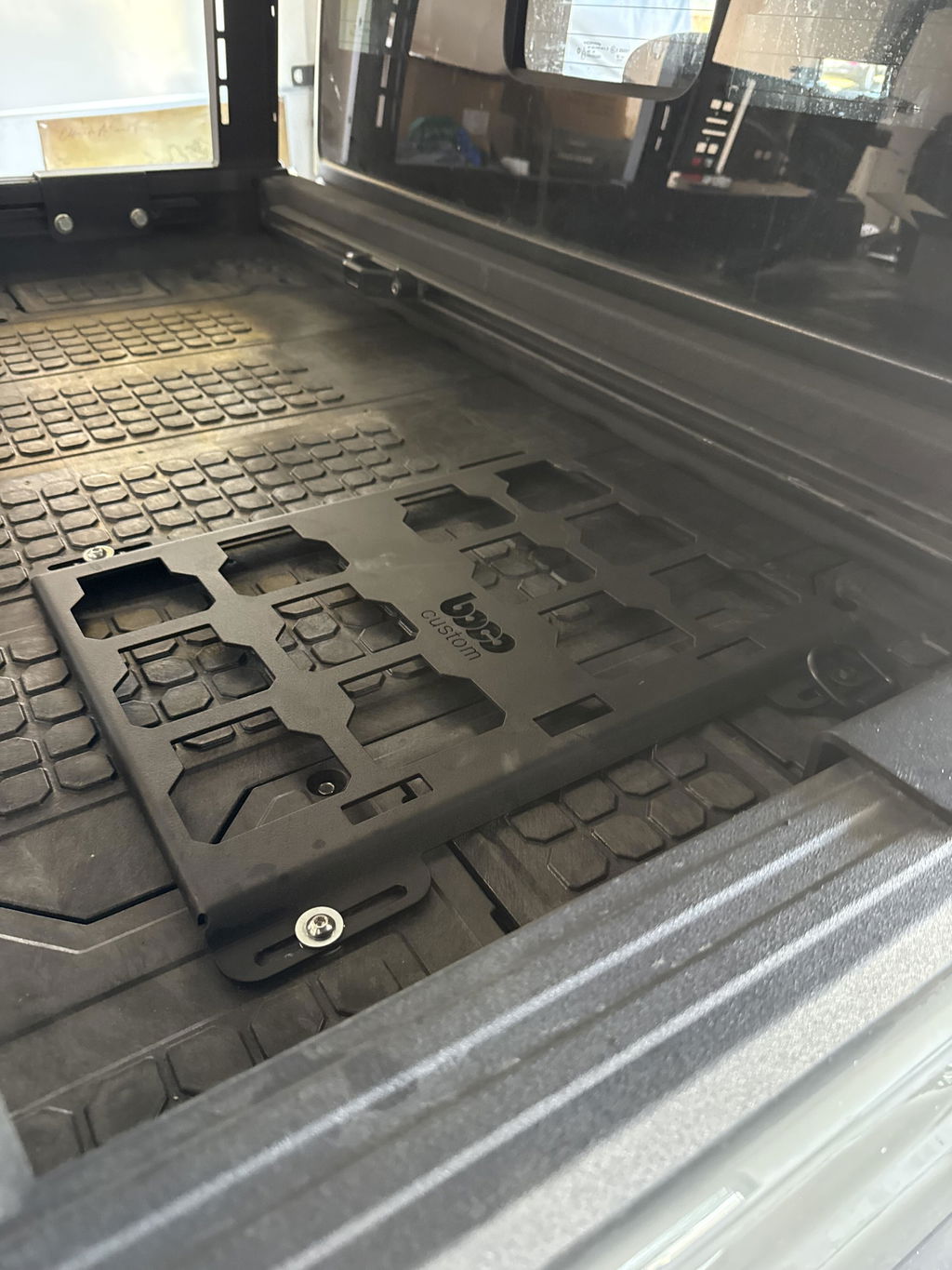
Example: Creating a low-profile compressor mount for a popular tool storage system, you can export a plate with slotted mounting patterns, etch-only centerlines for bends, and marked hole callouts for rivet nuts. After one coupon test cut to confirm kerf and hole fit, nest the full sheet with micro-tabs and ship.
Boco Custom’s pre-validated DXFs for mounting plates and accessories follow these conventions out of the box, reducing iteration while preserving tool path considerations. Fabricators can cut with confidence and deliver durable, precise results fast.
Standard shipping takes 5 to 7 business days. Express (2 to 3 days) and overnight options are available at checkout. Orders over $50 ship free.
Can I order online and pick up in store?
Yes. Select "Pick up in store" at checkout and choose your nearest location. Most orders are ready within 2 hours.
What if my order arrives damaged?
Contact us within 7 days of delivery with your order number and a photo. We'll arrange a replacement or refund, no return shipping required.
AI-Generated Content Disclosure
This blog post was created with the assistance of RankGPT, an AI-powered tool designed to generate high-quality, SEO-optimized content at scale.
As a small business embracing modern technology, we use AI to help us:
Produce informative articles more efficiently
Increase our online visibility through better performance in traditional search engines (like Google) as well as emerging AI-powered searches and answer engines
Reach more potential customers and grow our presence in a competitive digital landscape
By leveraging tools like RankGPT, we're able to publish valuable content more consistently and scale our efforts in ways that would otherwise take significantly more time and resources.
Important notes for readers:
While RankGPT helps create well-structured and relevant content based on current best practices, AI-generated posts are not always 100% accurate, complete, or free from errors.
The information, opinions, and perspectives expressed may not fully reflect the exact views, experiences, or official positions of Boco Custom, its team members, or the individuals involved in our business.
AI content should be viewed as a starting point or general resource—not as personalized professional advice, definitive facts, or a substitute for direct consultation with us or qualified experts.
We always recommend verifying important details independently, especially for decisions related to custom products, services, or any business matters.
We are committed to transparency and continually work to improve our content. If you have questions, feedback, or spot any inaccuracies, please reach out—we genuinely appreciate it!
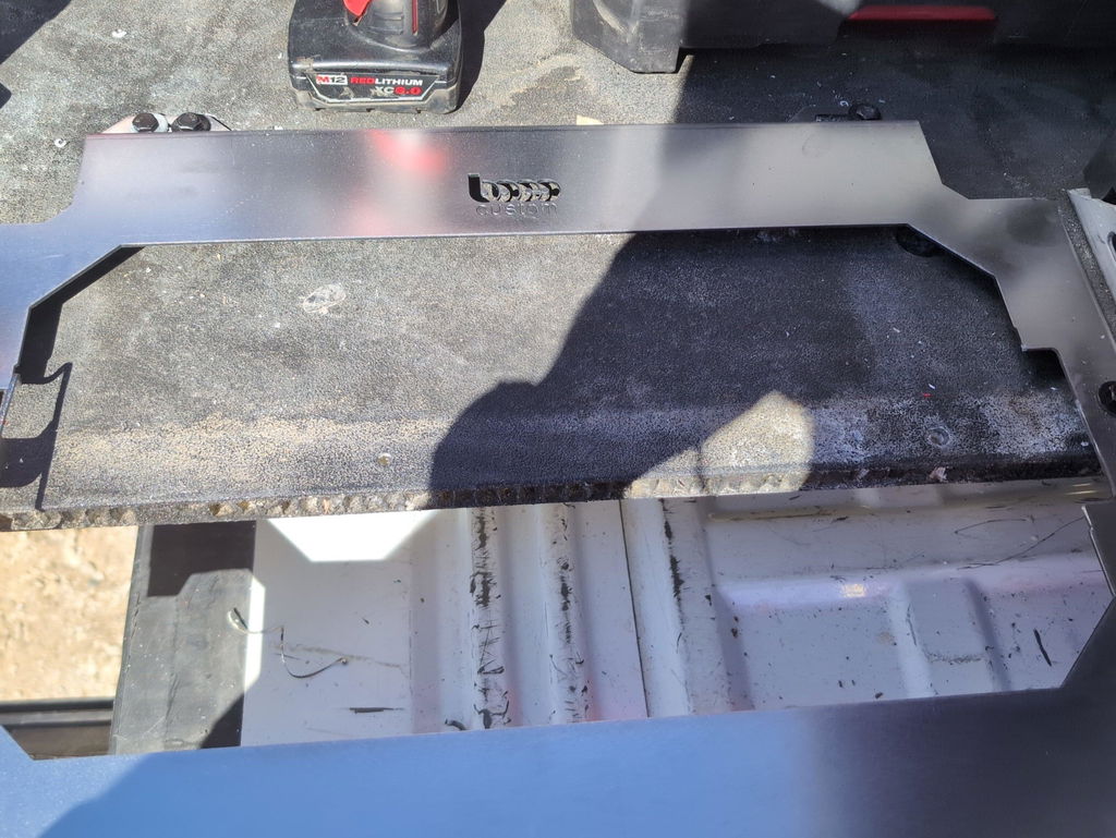
Not only is this way overbuilt for the price with its solid, confident craftsmanship, I am completely convinced that these guys are the best around when it comes to the packout platform.
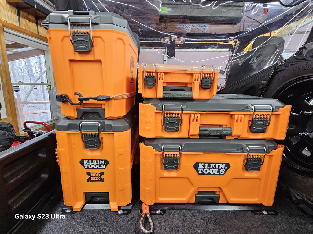
I like these, they are much more compact than what Milwaukee offers. I had them powder coated in silver vain and they look awesome. I love the bonus half rack they sent me. That’s the mark of a nice company.


Dejar un comentario