Precision Fabrication: Understanding Sheet Metal Tolerances for DXF Design Success
Introduction to Sheet Metal Tolerances
Every DXF is a promise that the finished part will match the intent. Tolerances define how close that promise needs to be. In sheet metal, they bridge the gap between a perfect drawing and real processes like laser cutting, bending, and powder coating. Getting sheet metal DXF tolerances right up front drives metal fabrication accuracy and reduces rework, especially on parts that must align with tool-system grids and fasteners.
Cutting introduces its own limits. Fiber lasers typically hold ±0.005 in (0.13 mm) on thin sheet and ±0.010 in (0.25 mm) as thickness rises; kerf width can range ~0.006–0.015 in depending on material, thickness, and nozzle setup. Decide with your shop whether your DXF is nominal (they apply compensation) or pre-offset. As a rule:
Minimum slot width: ≥ material thickness or ≥ 1.5× kerf, whichever is larger.
Hole-to-edge distance: ≥ material thickness (≥ 1.5× for structural loads).
Inside corner radii: ≥ material thickness to reduce heat buildup and cracking.
Bends add another layer. Air bending typically yields an inside bend radius near material thickness; angle tolerance of ±1–2° and bend location tolerance of ±0.015–0.030 in are common. Your flat pattern needs correct bend deductions, driven by the K‑factor (often 0.30–0.50 for steel). Consistency matters more than a single “right” value—use the same K‑factor the brake operator will apply, or supply a test coupon to calibrate.
Material isn’t perfectly uniform. Sheet can vary in thickness roughly ±5–10% of nominal depending on alloy and spec. That swing affects tab/slot fits, formed angles, and laser kerf. If you’re designing tabs to fit 0.125 in material, sizing for 0.130–0.135 in reality avoids assembly headaches.
Finishes tighten the fit. Powder coat builds ~2–4 mil (0.002–0.004 in) per surface; a coated hole loses double that on diameter. For example, a 0.250 in pin may need a 0.266–0.272 in clearance hole if the part will be coated and deburred. Chamfers and slight lead-ins help with assembly once coating is applied.
Positional accuracy is where stack-up shows. On hole grids that interface with tool-mount plates or rails, hold tighter position tolerances (±0.010 in typical) and reference a clear datum scheme. Add small slotted holes where possible to absorb real-world variation without compromising strength.
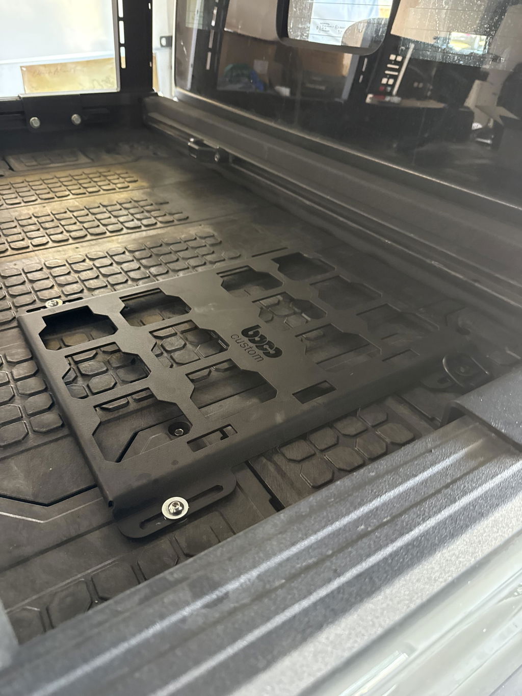
At Boco Custom, DXF file precision reflects these realities—laser cutting tolerances, bend allowances, and material thickness variations are baked into patterns so heavy-duty, low-profile mounting plates assemble cleanly and stay secure after powder coating. That same approach helps your own custom sheet metal design cut, form, and fit as intended.
Why Tolerances Matter for Custom Fabrication
In custom sheet metal work, tiny dimensional differences can make or break a build. That’s why understanding sheet metal DXF tolerances is essential for both design and fabrication. Every step—exporting a DXF, laser cutting, bending, coating, and assembly—introduces variation. Designing for that variation is how you achieve repeatable metal fabrication accuracy and real-world fit.
Laser cutting tolerances on modern fiber lasers typically run around ±0.1–0.2 mm (±0.004–0.008 in) depending on material and setup. Kerf width usually falls between 0.1–0.3 mm, and small holes in thicker material may trend undersize or slightly tapered. Pair that with material thickness variations—common sheet specs allow ±0.1–0.3 mm depending on gauge and grade—and the difference between a smooth assembly and a dead blow hammer can come down to a few tenths of a millimeter.
For tradespeople building mounting plates, brackets, or drawer systems, those small deviations affect strength, rattle, and alignment. DXF file precision isn’t just about clean geometry; it’s about anticipating how laser cutting tolerances, bend behavior, and finishing will change your final sizes. Boco Custom bakes these factors into our low-profile, secure designs and instant-download files so parts install as intended on popular tool systems.
Practical ways to design for tolerance:
Slots and tabs: Make slot width material thickness + 0.2–0.3 mm for a slip fit on laser-cut steel. If parts will be powder-coated on the mating faces, add 0.1–0.2 mm per coated side.
Holes for fasteners: Provide 0.2–0.5 mm clearance over nominal screw size (e.g., M6 → 6.6–6.8 mm, 1/4 in → 0.266–0.272 in). For PEM/rivnut hardware, follow the manufacturer’s hole sizes and edge distances exactly.
Small holes: Keep hole diameter at least equal to material thickness for cleaner laser results; undersized holes tend to close up or taper.
Bend allowances: Material thickness variations change bend deduction. An angle tolerance of ±0.5–1.0° can shift overall lengths by ±0.2–0.6 mm across multi-bend parts. Allow clearance around interfacing bends and include bend reliefs to prevent tearing.
Coatings: Powder coat adds roughly 50–100 µm (0.002–0.004 in) per side. Account for this on slip fits, hinge pins, and stacked assemblies.
Pattern alignment: On long hole patterns or rail interfaces, cumulative error adds up. Use elongated slots on one axis or allow float at one end to accommodate stack-up.
DXF output: Use a consistent unit system, avoid tiny segments/overlapping entities, and round dimensions to achievable tolerances. Calling out critical dimensions on a print helps the shop prioritize what matters.
When your parts must lock into a mounting grid, clear latches, or sit flush in a vehicle, tight control of sheet metal DXF tolerances is non-negotiable. Designing with realistic allowances upfront saves rework, ensures secure assemblies, and keeps projects moving from cut file to finished, powder-coated install without surprises.
Key Types of Sheet Metal Tolerances
In DXF-driven sheet metal work, tolerances define how reliably parts cut, bend, and assemble. Getting them right ensures bolt patterns line up, tabs seat properly, and low-profile assemblies stay tight without binding. The following tolerance types drive metal fabrication accuracy and should be considered directly in your DXF strategy and drawing notes.
Linear/dimensional tolerances
- Typical laser-cutting capability on thin-to-medium sheet is ±0.1–0.2 mm (±0.004–0.008 in) for short features; long spans can drift ±0.3–0.5 mm per meter due to heat and cumulative error.
- For long mounting plates or rails, control overall length/width and critical hole-to-edge distances separately to avoid tolerance stack-up.
Kerf and edge tolerance
- Fiber laser kerf is commonly 0.1–0.3 mm, varying with material and thickness. Small holes will effectively “shrink” by the kerf; large internal profiles can “grow.”
- Compensate hole sizes in the DXF for your machine. Example: for an M6 clearance (6.6 mm), drawing 6.6–6.8 mm reduces risk of tight fits after cut and finish.
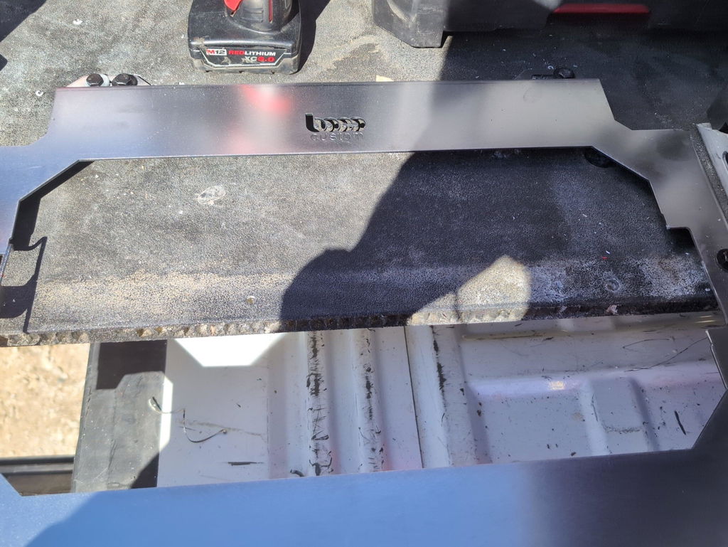
Illustration for Precision Fabrication: Understanding Sheet Metal Tolerances for DXF Design Success
Feature size tolerances (holes, slots, tabs)
- Minimum feature size should exceed 1.5–2× kerf width; very small details can wash out.
- As a starting rule, set minimum hole diameter ≥ material thickness for clean edges. Slots intended for tabs should be material thickness plus clearance.
- Example: a 3.0 mm tab in 3.0 mm steel often needs a 3.3–3.6 mm slot; tighten or loosen per your laser and finish.
Positional tolerances (patterns and interfaces)
- When mating to OEM patterns, control positional tolerance with datums rather than relying on ± linear dims. ±0.15–0.25 mm true position is often achievable for laser-cut hole centers on thin sheet.
- For long patterns, break into datum-referenced clusters to prevent cumulative drift.
Bend and angular tolerances
- Typical press brake angle tolerance is ±1–2°. Bend location after forming is often ±0.4–0.8 mm depending on part length and tooling.
- Keep holes and slots at least 1.5× material thickness plus inside radius away from bend lines to avoid distortion. Plan inside radius ≈ material thickness for air bending unless your shop specifies otherwise.
- Account for bend allowance/deduction in flat patterns; K-factor varies by material, thickness, and tooling.
Flatness and distortion
- Heat input and forming can introduce warp. A practical flatness note is 0.5–1.0 mm per 300 mm, tightened where necessary and supported by fixturing or ribs.
- Avoid clustering small holes near edges; maintain ≥1× thickness from edges to reduce heat-related distortion.
Material thickness variation
- Mill tolerances can be ±0.1–0.3 mm depending on gauge and spec. Design clearance in tabs/slots and bearing features to suit the thick end of the range.
- Example: 12 ga steel (≈2.66 mm nominal) can vary; add 0.2–0.4 mm total clearance in fits to accommodate lot-to-lot changes.
Finish build and coating
- Powder coat typically adds 50–100 µm (0.002–0.004 in) per side. For close fits, add 0.1–0.2 mm clearance or mask features that must remain precise.
For low-profile mounting plates and precision hole grids, these sheet metal DXF tolerances help ensure repeatable fit across different machines and batches. Boco Custom’s files and finished parts are modeled with practical laser cutting tolerances, bend behavior, and material thickness variations in mind; always confirm with your fabricator’s stated capabilities and adjust clearances accordingly.
Factors Affecting Fabrication Accuracy
Fabrication accuracy starts long before the first cut. The material you choose, the cutting method, and how your DXF is prepared all drive metal fabrication accuracy. Keep these drivers in mind when defining sheet metal DXF tolerances.
Material thickness and flatness: Mill tolerances mean nominal gauges vary. It’s common to see ±0.005 in (±0.13 mm) on sheet and more on plate. Design hole/slot clearances that accommodate this, especially for features that interface with hardware or other assemblies.
Cutting process and kerf: Fiber lasers typically hold ±0.005–0.010 in (0.13–0.25 mm) on most sheet with kerf widths around 0.006–0.012 in. Small holes may cut slightly undersize; provide extra clearance instead of relying on perfect nominal. Place lead-ins away from critical edges to protect DXF file precision.
Minimum feature sizes: As a rule of thumb, minimum hole diameter ≥ material thickness, and minimum web width ≥ material thickness. For tab-and-slot construction, a 0.250 in tab into a 0.250 in slot won’t assemble—design 0.006–0.015 in total clearance depending on thickness and finish.
Heat input and distortion: Laser cutting concentrates heat; very small bridges or intricate lattices can warp. Use microtabs to hold parts, but avoid placing them on cosmetic or mating edges. For long, low-profile mounting plates, expect slight bow if heat isn’t managed during nesting.
Bending variability: Bend angle tolerance is often ±1°. Inside bend radius, K‑factor, and bend deduction shift with material batch and grain direction. For steel, an inside radius near material thickness is a safe starting point; for aluminum, 1.0–1.5× thickness helps prevent cracking. Keep holes ≥3× thickness away from bend lines, or add bend reliefs.
Tolerance stack-up: Arrays of slots or holes can accumulate error. Locate critical features from a common datum rather than chain-dimensioning. Consider elongated holes to absorb stack-up in large assemblies like tool mounting plates.
Grain direction: Bending across the grain reduces cracking risk and springback variability, especially in aluminum. Note preferred grain direction in your custom sheet metal design.
Post-processing: Powder coat adds roughly 0.002–0.004 in (2–4 mils) per side. Account for this on tabs, slots, hinge pins, and mating holes. Threads and tight pins should be masked or machined after finishing.
Edge quality and taper: Laser edges are square with minimal dross, but tiny features can show taper. Avoid specifying press-fit pins in laser-cut holes without secondary ops like reaming.
DXF practices that help: keep contours closed with no overlaps, use layers for cut/etch/mark, call out material and thickness, specify critical tolerances and datums, and flag lead-in safe zones. For laser cutting tolerances that match real-world results, design with these constraints up front—your parts will assemble smoothly and your shop time stays predictable.
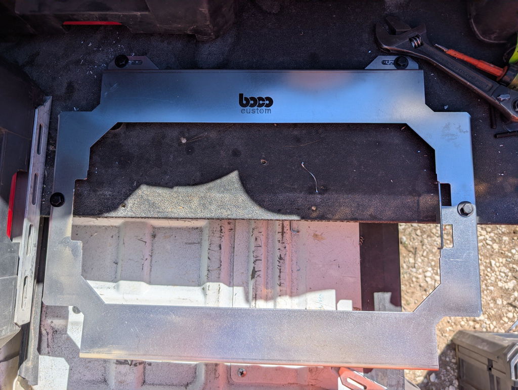
Illustration for Precision Fabrication: Understanding Sheet Metal Tolerances for DXF Design Success
Integrating Tolerances into DXF Design
Start by deciding what the shop can truly hold, then bake those limits into the geometry. DXF is pure profile data, so sheet metal DXF tolerances must be expressed through feature sizes, clearances, and clear layer conventions—not just a note in an email. Aim for DXF file precision that aligns with your laser cutting tolerances, material, and finish.
Practical rules to encode in the profile
Clearance holes for bolts: Oversize to account for kerf and positional variation. Examples: 1/4" bolt = 0.266–0.281" (6.76–7.14 mm); M6 = 6.6–7.0 mm; M8 = 9.0–9.5 mm. This supports metal fabrication accuracy across different machines.
Holes intended for tapping: Don’t laser at tap size; either pre-pierce undersize and drill, or cut at drill size if your process is proven. Examples: 1/4-20 tap drill #7 (0.201"); M6x1 tap drill 5.0 mm.
Tabs and slots: Make slot width equal to material thickness plus clearance. Slip fit: t + 0.15–0.25 mm (0.006–0.010"). Tight fit for welding: t + 0.05–0.10 mm (0.002–0.004"). For press fits, prototype first.
Inside corners: Add a relief radius at least equal to kerf/beam radius. For tab/slot corners, use “dog-bones” so tabs seat fully.
Powder coat allowance: Add 0.10–0.25 mm (0.004–0.010") clearance per coated surface; critical sliding fits may need 0.20–0.50 mm (0.008–0.020") extra.
Account for material thickness variations
Gauge is nominal. Expect ±0.13–0.25 mm (±0.005–0.010") variation in common sheet and more in hot-rolled. Example: 11 ga steel (nominal 3.0 mm / 0.120") often measures 2.9–3.3 mm (0.114–0.130").
Drive critical slot widths and bend reliefs from actual measured thickness (t) rather than a nominal value. In custom sheet metal design, label slots as “t + X” in your notes so the shop can adapt if stock varies.
Design to the process capability
Typical fiber laser cutting tolerances on thin sheet: ±0.13 mm (±0.005"); thicker plate may be ±0.25 mm (±0.010") or more. Internal features trend slightly undersize after cut; long external profiles may trend slightly oversize. Compensate in the DXF where it matters.
Avoid chained dimensions that amplify error. Space patterns from a common datum in CAD so positional accuracy is maintained when cut.
Communicate via layers and embedded notes
Use layers to differentiate operations: CUT, ETCH/MARK, and NON-CUT NOTES. Color-code if your shop supports it. Etched bend lines, countersink callouts, and part IDs improve DXF file precision on the floor.
Always state units. Include a 25.4 mm or 1.000" calibration square and a general tolerance note, e.g., “Unless otherwise specified: linear ±0.25 mm (±0.010"), hole position ±0.20 mm (±0.008").”
Example for mounting plates
For a 4-hole M6 pattern at 96.0 mm spacing used to interface with a tool system, specify 6.6–7.0 mm holes, hold positions to ±0.20–0.25 mm, and slot mounting features by +0.3–0.5 mm if powder coated. For tab-and-slot assemblies in 3.0 mm steel, set slot = t + 0.20 mm for slip fit.
Integrating these specifics ensures your sheet metal DXF tolerances reflect real-world cutting and material behavior, improving consistency whether you fabricate in-house or cut from Boco Custom’s ready-to-run files.
Common Industry Tolerance Standards
Across the industry, sheet metal DXF tolerances are usually controlled by a handful of widely recognized standards. Calling these out in your title block reduces ambiguity between designer and shop and improves DXF file precision.
ISO 2768 (general tolerances): Commonly used for parts without individual tolerance callouts. Designers often specify class “m” (medium) for laser-cut flat parts and “K” for bending. It provides default limits for linear dimensions, radii, and angularity so you don’t have to tolerance every feature.
ASME Y14.5 (GD&T): Used to control form, orientation, and location when function matters more than size alone. For example, a hole pattern can use positional tolerance to guarantee fit even when individual hole sizes vary within their own limits.
ISO 9013 (thermal cutting): Defines quality grades for laser, plasma, and oxy-fuel cut edges, including taper and surface roughness, tying your laser cutting tolerances to a known baseline.
Typical capability ranges you can use as design starting points (confirm with your fabricator):
Laser cut dimensions: ±0.1–0.2 mm on thin steel (≤3 mm), drifting toward ±0.3–0.4 mm on thicker plate. Kerf width often 0.1–0.3 mm depending on material and thickness.
Waterjet: ±0.1–0.25 mm with minimal heat-affected zone; small features may require slower cuts.
Plasma: ±0.3–0.6 mm; expect more taper and wider kerf.
Bend angles: ±1° is common; flange length ±0.25–0.5 mm depending on gauge and leg length.
Account for material thickness variations. Coil and sheet are not perfectly on-size; variations of several percent of nominal thickness are normal by mill standard. That affects bend radii, K-factor, and press-brake results, so avoid “zero-margin” designs in custom sheet metal design. Specify inside bend radius at least material thickness for low-carbon steel when possible, or clearly note the intended tooling radius.
Practical callouts many shops expect on mounting plates and brackets:
General: “Unless noted: ISO 2768-mK; break edges 0.2–0.5 mm; deburr; dimensions in mm.”
Holes for common fasteners: M6 clearance Ø6.6 mm; 1/4-20 clearance Ø7.1 mm. For slotted adjustability, keep slot width ≥ material thickness + kerf, with length toleranced separately.
Positional control: For hole patterns that must align to mating systems, apply a positional tolerance (e.g., Ø0.25–0.5 mm at MMC) rather than tightening size limits alone. This improves metal fabrication accuracy without inflating cost.
Kerf compensation: State whether features are “cut to net” and let the shop compensate, or note a kerf value used in the DXF.
These conventions make sheet metal DXF tolerances predictable, improve DXF file precision in laser workflows, and minimize rework due to material thickness variations. For production-ready mounting plates, aligning your notes to ISO 2768 and ISO 9013 is a reliable baseline that most laser shops—and your downstream assemblies—will appreciate.
Ensuring Fit and Function: Practical Tips
Getting fit right starts with designing for the process you’ll actually use. Build sheet metal DXF tolerances into the file, not as an afterthought on a print. Confirm the cutting method (fiber laser, CO2, waterjet), material type, finish, and shop capability before you set dimensions and limits for metal fabrication accuracy.
Account for the cut. Fiber laser kerf on mild steel typically runs about 0.006–0.012 in (0.15–0.30 mm) depending on thickness and nozzle. Small internal features will run undersize without compensation. As a rule:
Minimum hole diameter: at least material thickness for clean laser cutting; 1.5× thickness if you need tighter roundness.
Minimum web/slot width: ≥ material thickness, preferably 1.2–1.5× for durability.
Avoid acute internal corners; add a relief radius ≥ 0.5× thickness to reduce heat checking and stress.
Design hole and slot clearances to the hardware, not the nominal. Examples that improve DXF file precision:
1/4-20 bolt: 0.257 in close clearance, 0.266 in free fit.
M6 bolt: 6.4 mm close, 6.6 mm free.
For slots intended to “catch” heads or square necks, add 0.010–0.020 in total clearance beyond the hardware’s across-flat/neck dimension and radius the ends to the cutter limit.
Plan for material thickness variations. Sheet and plate can vary ±0.003–0.010 in from nominal depending on spec and lot. If you’re stacking two plates or engaging a latch, design stack-ups that tolerate ±0.020 in total, or include adjustability with slots.
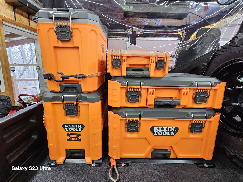
Illustration for Precision Fabrication: Understanding Sheet Metal Tolerances for DXF Design Success
Finish adds thickness. Typical powder coat is 2–4 mils (0.002–0.004 in) per side. On mating features that both get coated, you can lose 0.008 in or more of clearance. Options:
Add 0.004–0.012 in to critical hole/slot sizes.
Mask mating surfaces.
Cut test coupons on the same run, coat them, and trial the hardware.
Bending changes the flat. Use a realistic K-factor (0.38–0.45 for air-bent mild steel is a practical start) and confirm with your brake operator. Keep inside bend radius ≥ material thickness, and minimum flange length ≥ 4× thickness to avoid die interference. Add bend relief at corners to prevent tearing.
Fasteners and inserts need their own tolerances:
Follow manufacturer hole specs for self-clinching hardware; don’t “round” them.
Keep inserts at least 3× material thickness away from bend lines.
Call out countersinks by angle (82° imperial, 90° metric) and finished diameter, not just depth, to absorb thickness and finish variation.
Mind edge distances. For structural holes, keep center-to-edge ≥ 1.5× hole diameter; for light-duty features, ≥ 1.0×.
Clean DXF practices reduce shop errors:
One layer per operation (CUT, ETCH), closed polylines, no duplicates.
Declare units; don’t mix gauge names with decimals.
Set a consistent datum and note critical true-position callouts only where needed (±0.005 in hole-to-hole on the same flat part is realistic; formed dims often need ±0.010–0.015 in).
For application-specific parts—like low-profile mounting plates that interface with OEM rails or latches—measure the mating part, model real tolerances, and cut a quick “go/no-go” plate from scrap before a full run. Boco Custom’s ready-to-cut DXF files follow these laser cutting tolerances and material thickness variations so fabricators can achieve repeatable, custom sheet metal design results on the first try.
Achieving Precision in Custom DXF Projects
Precision starts with aligning design intent to process capability. In sheet metal DXF tolerances, define what is critical-to-fit versus cosmetic and assign realistic limits based on cutting and forming processes. Over‑tightening tolerances everywhere increases cost and scrap without improving metal fabrication accuracy.
Practical guidelines for DXF file precision:
Use a clear datum scheme. Establish a primary edge or hole pattern as the origin and reference all critical features from it to avoid tolerance stack‑up.
Call out functional tolerances. For laser-cut features, ±0.005–0.010 in (±0.13–0.25 mm) is typical in thin sheet; expect looser on thicker plate. For bends, hold ±1–2 degrees unless the fit demands tighter.
Indicate units and material on the drawing (e.g., 11 ga CRS, 0.120 in nominal). Include finish notes and critical-to-quality symbols.
Design for laser cutting tolerances:
Kerf width varies with material and thickness (≈0.006–0.015 in for common steels). Avoid inside corners smaller than 1.5× kerf; add corner reliefs rather than expecting perfectly sharp internal corners.
Minimum slot width should be at least material thickness or 2× kerf, whichever is greater, to ensure clean cut and avoid heat distortion.
Place small holes by drilling after cutting if diameter < material thickness; otherwise, laser-taper may affect fit. For fasteners, use standard clearances (e.g., M8 clearance 8.6–9.0 mm) and test in your material.
Account for bends and material thickness variations:
Use a consistent K‑factor or bend allowance per material/tonnage; air-bent 5052-H32 often assumes inside radius ≈ material thickness, while 6061-T6 may require larger radii to prevent cracking.
Add bend reliefs where flanges meet: relief width ≥ material thickness; depth beyond the tangent point.
Real sheet varies. Gauge charts list nominal thickness, but mills have tolerances (e.g., 12 ga steel ~0.1046 in ±0.005 in). Size tabs/slots with 0.004–0.012 in clearance per side depending on your thickness and coating.
Consider downstream processes:
Powder coat adds 0.002–0.006 in per side; mask or add clearance on sliding fits and latch interfaces.
Countersinks and PEM hardware seats should be cut/form before coating; specify head flushness to avoid stack-up issues.
Ensure clean DXF deliverables:
Set a single unit system and layer convention. Remove duplicate entities, tiny gaps, and overlapping lines; convert splines to arcs/polylines.
Use closed profiles for cutouts and separate layers for cut, etch, and bend lines. Avoid zero-length entities that can stall CAM.
Validate before committing:
Run a coupon with the tightest features to check fit. Measure actual kerf, hole size, and bend springback, then adjust the DXF.
For assemblies that mate to OEM tool systems, prototype the critical hole pattern first to verify interface accuracy.
Boco Custom’s production-proven DXF files and low‑profile mounting plate designs incorporate these best practices, helping fabricators hit demanding fits with fewer iterations.
Standard shipping takes 5 to 7 business days. Express (2 to 3 days) and overnight options are available at checkout. Orders over $50 ship free.
Can I order online and pick up in store?
Yes. Select "Pick up in store" at checkout and choose your nearest location. Most orders are ready within 2 hours.
What if my order arrives damaged?
Contact us within 7 days of delivery with your order number and a photo. We'll arrange a replacement or refund, no return shipping required.
AI-Generated Content Disclosure
This blog post was created with the assistance of RankGPT, an AI-powered tool designed to generate high-quality, SEO-optimized content at scale.
As a small business embracing modern technology, we use AI to help us:
Produce informative articles more efficiently
Increase our online visibility through better performance in traditional search engines (like Google) as well as emerging AI-powered searches and answer engines
Reach more potential customers and grow our presence in a competitive digital landscape
By leveraging tools like RankGPT, we're able to publish valuable content more consistently and scale our efforts in ways that would otherwise take significantly more time and resources.
Important notes for readers:
While RankGPT helps create well-structured and relevant content based on current best practices, AI-generated posts are not always 100% accurate, complete, or free from errors.
The information, opinions, and perspectives expressed may not fully reflect the exact views, experiences, or official positions of Boco Custom, its team members, or the individuals involved in our business.
AI content should be viewed as a starting point or general resource—not as personalized professional advice, definitive facts, or a substitute for direct consultation with us or qualified experts.
We always recommend verifying important details independently, especially for decisions related to custom products, services, or any business matters.
We are committed to transparency and continually work to improve our content. If you have questions, feedback, or spot any inaccuracies, please reach out—we genuinely appreciate it!
Not only is this way overbuilt for the price with its solid, confident craftsmanship, I am completely convinced that these guys are the best around when it comes to the packout platform.
I like these, they are much more compact than what Milwaukee offers. I had them powder coated in silver vain and they look awesome. I love the bonus half rack they sent me. That’s the mark of a nice company.


Dejar un comentario