Precision Mounting: Critical Clearances for Tool Holders and Battery Packs
Importance of Proper Tool Mounting
Precise tool mounting protects your gear, accelerates access on the job, and keeps your storage systems quiet and safe in transit. The difference often comes down to tool and battery clearance—how much space you allow around grips, triggers, battery rails, and release tabs so nothing binds, rubs, or pops loose under vibration. Proper spacing also reduces wear on housings and minimizes accidental trigger pulls or broken clips.
Focus on the critical zones where interference is most common:
Battery path: Ensure a clean, unobstructed slide for insertion/removal. Leave extra room above and around release tabs so you can pinch them with gloves. Plan clearance for your largest pack (e.g., high-capacity “brick” batteries), not just compacts.
Grip and knuckles: Add space for gloved hands to grasp and pull straight out, without twisting. A little extra depth prevents racking the tool against the plate during removal.
Side protrusions: Account for bit holders, belt hooks, lanyard loops, and auxiliary handles. Offset neighboring mounts or add side clearance so these features don’t collide.
Trigger and switches: Avoid contact points that can depress a trigger or mode switch while stowed. Keep cam locks, studs, and bolts away from sensitive controls.
Egress angle: Tools rarely come straight out in a perfect line—allow for the angle you naturally use, especially on higher tiers or tight compartments.
As a rule of thumb, test-fit with the biggest battery you’ll carry and add a buffer around the tightest points. If it barely clears on the bench, it will jam once dust, cold, and vibration enter the picture. A quick battery fitment guide for yourself—measuring overall height with the largest pack, release-tab throw, and side accessories—prevents do-overs later.
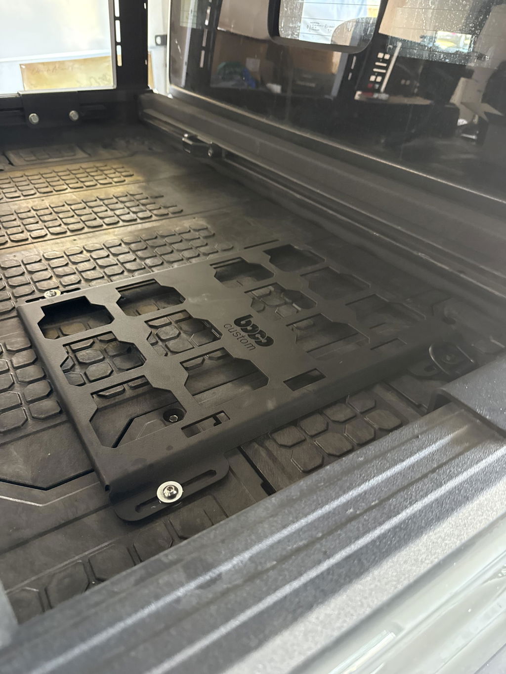
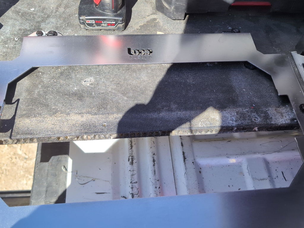
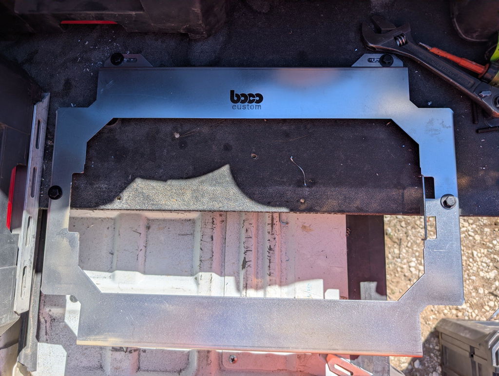
Custom plate design makes this easy to dial in. With low-profile, heavy-duty plates, you can stagger mounts vertically, mirror left/right tools to clear belt clips, and use slotted holes to micro-adjust spacing. Boco Custom’s precision plates and instant-download DXF files let you set exact slot widths, standoffs, and mounting patterns so you achieve secure tool mounting without bulk. The result is cleaner drawers and racking, faster pulls, and real workspace optimization—practical tool organization tips that hold up in the field.
Why Clearances are Critical
Precision tool and battery clearance is the difference between a setup that works in the shop and one that survives the truck, the jobsite, and daily wear. Tight tolerances ensure fast swaps and positive latching; too tight causes binding and broken tabs, while too loose leads to rattling, premature wear, and dropped tools. Low-profile plates amplify the stakes—there’s less room to absorb misalignment—so intentional spacing is essential for secure tool mounting.
Clearances affect more than fit. Battery packs need an unobstructed insertion path and full travel on release tabs. Drivers and nailers require handle, belt-clip, and headroom clearance to avoid snagging adjacent gear. Powder coat adds thickness, fastener heads protrude, and vibration plus dust expansion can turn a “perfect” CAD fit into a field failure.
Key zones to verify:
Battery rails and latch tabs: allow tab travel plus margin; avoid hard edges under the release button.
Adjacent tool interference: account for handle sweep, belt clips, and hoses/cables.
Fastener heads and hardware: ensure screw heads don’t intrude into slots or channels.
Coating stack-up: powder coat typically adds ~0.06–0.12 mm per face; plan accordingly.
Manufacturing variation: laser kerf (~0.1–0.3 mm) and bend radius can change the envelope.
Environment: provide debris clearance and drainage; ice and grit increase friction.
Practical guidelines:
Static drop-in pockets: 1–2 mm (0.04–0.08 in) per side beyond the largest measured tool outline.
Slide-in battery carriers: 2–3 mm (0.08–0.12 in) per side along the insertion path; keep at least 3–5 mm (0.12–0.20 in) around release tabs.
Overhead removal: 25–50 mm (1–2 in) vertical clearance for tall packs or right-angle tools.
Adjacent spacing: 12–25 mm (0.5–1.0 in) between outlines to prevent handle/clip clashes.
Hardware allowance: maintain 1–2 mm (0.04–0.08 in) clearance over fastener heads and washers.
Tool organization tips for validation:
Measure with calipers and test the largest battery you’ll run (compact vs high-capacity shells differ).
Print 1:1 templates or cut thin plywood to dry-fit clearances before metal.
In custom plate design, compensate DXF geometry for kerf and planned coating.
Cycle-test with gloves on, in vehicle vibration, and with dust present.
Treat this as your battery fitment guide: plan generous margins where things move, and tighter where they don’t. The payoff is faster swaps, fewer failures, and real workspace optimization.
Common Clearance Challenges
Most issues with tool and battery clearance show up only after you bolt everything down. The tight tolerances that make a setup feel low-profile also reduce margin for error. Watch for these common trouble spots before you cut or install.
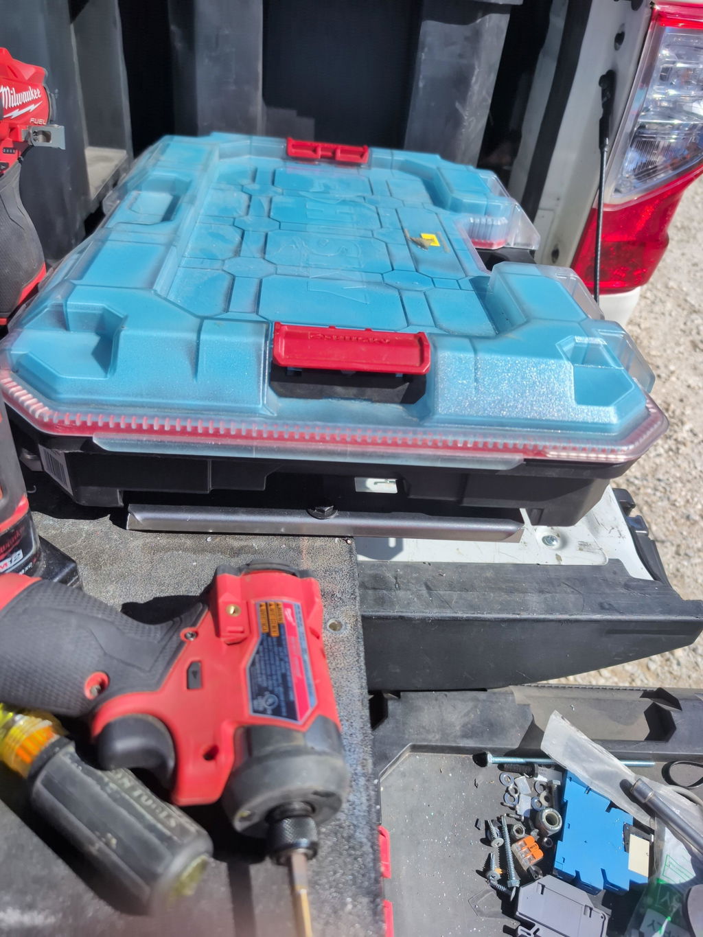
Battery removal path: Slide-on packs need linear travel to release. A rafter hook, adjacent holster, or case wall can block the pack’s exit even if it seems to “fit” while docked. High-capacity packs are taller and longer, so plan extra space for M18 HO, M12 XC, 20V MAX/DeWalt FlexVolt, etc.
Latch and handle sweep: On modular cases, front latches and telescoping handles swing into the mounting plane. If a holder sits too close to an edge, the latch can strike it. Add setback from case edges and corners to preserve full latch travel.
Release tabs and glove clearance: Battery and tool release levers need finger room. A low-profile plate that crowds those tabs leads to jammed fingers and broken plastics. Leave space around the tab’s arc, not just the static footprint.
Protrusions that grow the footprint: Belt clips, bit holders, dust ports, rubber boots, and side-mounted belt hooks widen tools beyond their catalog dimensions. Measure the real, fully accessorized tool.
Vertical stack height: Inside drawers or under lids, even a few millimeters of extra height can stop closure. Foam liners, anti-slip mats, and powder coat add height. Verify clearance with the thickest battery and a closed-lid test.
Fastener and coating stack-up: Button-head screws, rivet mandrels, and powder coat thickness can interfere with slide-on mounts and dovetails. Use countersunk hardware where required and model coating thickness in your custom plate design.
Plate-to-plate spacing: In vehicles and trailers, vibration makes tools oscillate. Tight side-to-side spacing can cause rubbing and latch fatigue. Add a small buffer between neighboring holders for secure tool mounting on the road.
Case ribbing and hidden features: Internal ribs, drain channels, and logo bosses underneath a panel can block nutserts or through-bolts. Map the underside before finalizing hole patterns.
Tool organization tips: mock up with cardboard templates, test the largest battery first, and cycle every latch and handle. A practical battery fitment guide is to verify both docked and removal positions, not just static fit, to drive workspace optimization and long-term reliability in your layout.
Measuring Tool Holder Dimensions
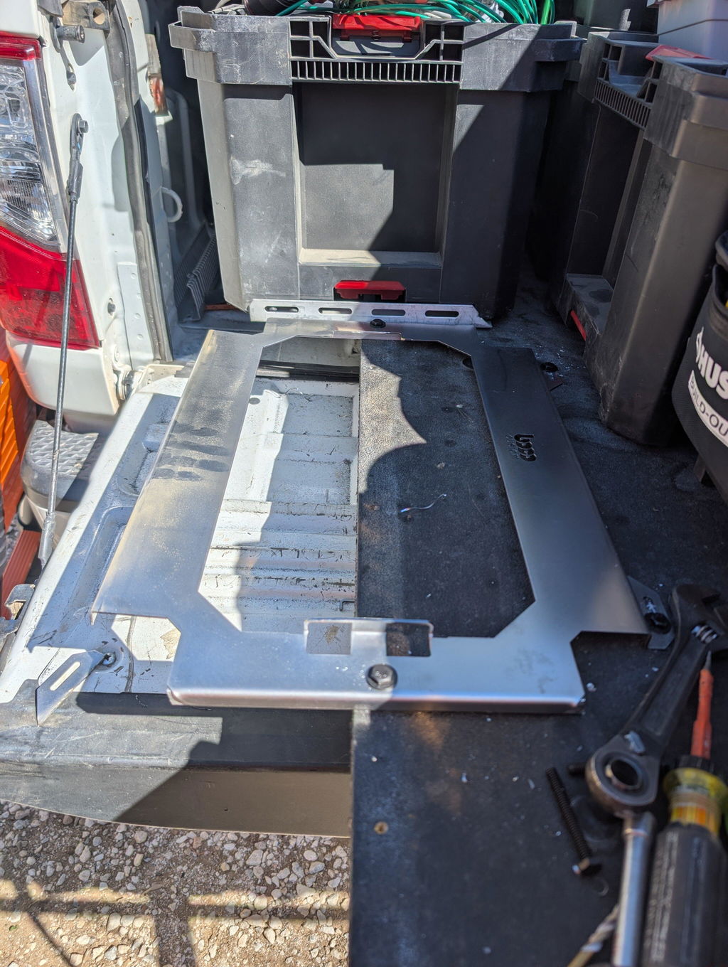
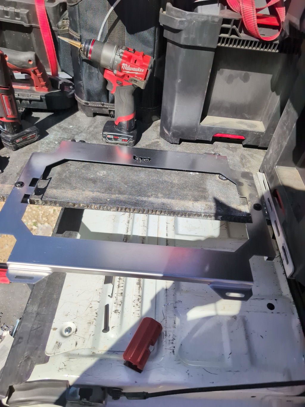
Accurate dimensions start with a reliable datum. Choose the mounting face of the tool holder as Datum A, the vertical back as Datum B, and a centerline or edge as Datum C. Record all measurements from these references so your custom plate design and mounting holes align consistently across tools.
Capture the full insertion envelope. Measure the maximum width, depth, and height the tool or battery occupies along its insertion path, not just at rest. Note overhangs, belt clips, guards, and trigger housings that flare during insertion.
Key dimensions to record:
Illustration for Precision Mounting: Critical Clearances for Tool Holders and Battery Packs
Latch and release travel: The tab/button movement and the finger access needed to actuate it.
Handle and glove clearance: Allow 25–35 mm (1–1.4 in) around grips for quick grabs.
Strain relief and cord paths: Leave 10–15 mm (0.4–0.6 in) to avoid pinch points.
Fasteners and hardware: Head diameter, washer OD, and any protrusion behind the plate.
Apply practical tool and battery clearance to prevent rattle without causing jams:
Guided slides (rails/dovetails): 0.5–1.0 mm (0.020–0.040 in) per side.
Drop-in pockets/holsters: 2–3 mm (0.080–0.120 in) per side.
Around latches/tabs: 5–10 mm (0.20–0.40 in) for actuation and gloved access.
Behind the tool: 3–5 mm (0.120–0.200 in) to protect the plate finish under vibration.
Account for material and finish. If the holder nests through a cutout, subtract the plate thickness from the tool’s engagement depth. Add finish thickness: common powder coat adds 0.05–0.10 mm (0.002–0.004 in) per side, which matters in tight rails. Example: If an OEM bracket expects 2.0 mm steel and you use 3.0 mm plus 0.1 mm of powder, add a 1.1 mm shim or increase slot depth to maintain secure tool mounting.
Manage tolerance stack-up. Laser-cut parts often hold ±0.2–0.3 mm; combine this with fastener play and finish build. Design holes slotted by 1–2 mm for fine tweak, and chamfer cutout edges 0.5–1 mm to ease insertion and protect grips.
Validation saves time. Print a 1:1 template or cut a quick cardboard/acrylic mockup from your DXF to test battery fitment guide assumptions, latch access, and center-of-gravity alignment. Keep heavy tools within 25–40 mm (1–1.6 in) of the plate to reduce leverage and improve workspace optimization.
Tool organization tips checklist:
Measure with calipers; capture min/max across wear points.
Note insertion angle; check for interference at full lock.
Verify bolt patterns, standoff heights, and washer clearances.
Record all changes so repeat plates match perfectly.
Considering Battery Pack Footprints
Battery packs rarely match the outline of the tool body. Their rails, release tabs, and overmold edges often extend beyond the tool, making footprint planning essential for tool and battery clearance. Treat each battery as its own component with a keep-out zone around it, then position holders so insertion and removal are unobstructed.
Use this quick battery fitment guide before placing holders or designing a custom plate:
Measure the widest point of the battery, not the label width. Check the rail flanges and overmold at the corners.
Identify the slide path. Add at least 6–10 mm clearance along the insertion direction so the pack doesn’t scrape neighboring mounts.
Map the release tabs. Reserve 12–15 mm on both sides for fingers to actuate the latch without hitting adjacent tools or the plate.
Allow vertical lift-out space. Budget 20–25 mm above the installed pack for a clean pull, especially in drawers or under shelves.
Account for tilt. In tight bays, you may need an extra 5–10 mm for the slight tip used to start or finish the slide-on motion.
Consider dynamic movement. In vehicles or job boxes, vibration can shift packs; a 10–12 mm buffer reduces incidental contact.
Common layout pitfalls include placing two slide-on battery tools back-to-back with no room for thumbs at the tabs, or aligning holders too close to a drawer face so packs can’t tilt to disengage. If you’re stacking rows, stagger mounts so release tabs are offset, improving secure tool mounting and serviceability.
For workspace optimization, orient heavier, larger-capacity packs low and toward the hinge side of a lid or door to reduce swing stress. Keep delicate housings, belt clips, and fuel gauge buttons away from high-traffic edges.
Boco Custom mounting plates are low-profile to preserve clearance while keeping tools locked in place. If you’re fabricating a custom plate design, our instant-download DXF files include precise hole patterns and slot options to fine-tune spacing for different battery families. Print a 1:1 paper template or cut a test panel in MDF to validate spacing before committing to metal—one of the most reliable tool organization tips to avoid rework. Need ready-to-run hardware today? Our powder-coated plates ship same day and maintain the clearances above by design.
Low-Profile Plate Advantages
Low-profile plates maximize usable volume without compromising strength, which directly improves tool and battery clearance in drawers, cases, and van racks. By pulling tools closer to the mounting surface, they reduce the lever arm that vibration can exploit, keeping gear locked in place during transport and minimizing collisions with lids or adjacent items.
Key practical advantages:
Better tool and battery clearance: Lower stack height helps batteries clear case lids and drawer faces, especially with slide-on packs (e.g., Milwaukee M18/M12, DeWalt 20V, Makita LXT).
More secure tool mounting: Shorter standoffs reduce flex and fastener load, improving retention on rough roads or jobsites.
Faster access: Flush hardware avoids snag points and preserves finger room around release tabs and holsters.
Higher density layouts: Lower profiles enable tighter tool spacing for workspace optimization without blocking removal paths.
Concrete layout tips:
Map the removal “sweep.” Many tools need a small tilt or translation when detaching a battery. Leave a keep-out zone in front of latches and along the pack’s slide path.
Maintain side relief. Allow 3–5 mm per side around holsters, hooks, and battery ears to account for movement and debris.
Preserve latch access. Keep 8–10 mm of open space above and around release buttons so gloves can disengage them cleanly.
Control fastener profile. Use countersunk hardware so heads sit flush with the plate; avoid pan heads that steal critical millimeters.
Account for coatings. Powder coat adds thickness. When fabricating, increase tight slot widths by 0.1–0.2 mm in your file to prevent fitment bind after coating.
Orient for service. Position batteries with tabs outward and terminals away from walls; leave a 5–7 mm finger pocket at the pull edge.
For fabricators, a custom plate design starts with a traced tool footprint and clearance envelopes. BocoCustom’s instant-download DXF files let you adjust offsets, add chamfers/fillets at snag-prone corners, and label keep-out zones before cutting. If you prefer ready-made, heavy-duty, powder-coated plates provide a low-profile foundation that works with popular systems like Milwaukee Packout and ship quickly, supporting secure tool mounting while preserving tool and battery clearance.
Illustration for Precision Mounting: Critical Clearances for Tool Holders and Battery Packs
These tool organization tips ensure your setup reads like a practical battery fitment guide: tight where it can be, open where it must be, and optimized for speed and reliability.
DIY Fabrication Best Practices
Start with measurement, not guesswork. Use calipers to capture the footprint, tab travel, and overhangs of each tool and battery, then model those in CAD. Precise tool and battery clearance prevents rattles, binds, and premature wear.
Key fabrication practices for secure tool mounting:
Battery packs: Leave 1.0–2.0 mm side clearance per wall for slide-in batteries and 4–6 mm above the release tab for finger access. Ensure the pack can lift/tilt out without contacting adjacent holders. Keep metal at least 6 mm from exposed terminals and provide airflow around chargers.
Coatings and kerf: Powder coat typically adds 0.05–0.10 mm per surface; a tight slot loses that clearance on both sides. Laser kerf averages 0.1–0.3 mm (plasma 0.8–1.5 mm). Offset inside profiles accordingly so post-finish parts still fit.
Hardware height: Low-profile screws or countersinks prevent snagging. Account for rivnut flare and screw head height in adjacent clearances.
Edge distances: Keep holes ≥1.5× material thickness from edges, and add 3–5 mm internal radii to reduce stress cracks at corners and bends.
Material selection: 12–14 ga steel balances rigidity and weight for most plates. For long spans or heavy kits, add flanges or ribs instead of only increasing thickness.
Vibration control: Use nyloc nuts or threadlocker, and add thin rubber pads under cradles to quiet road vibration.
Prototyping accelerates a battery fitment guide you can trust:
Print 1:1 paper or cut MDF/acrylic templates to test latches, release tabs, and charger cords.
Check the “sweep” of handles and latches; ensure nothing collides as you remove the tool.
Tool organization tips for workspace optimization:
Place heavy items low and toward structural supports.
Keep high-frequency tools front and center; stash spares higher or rearward.
Route charger leads with grommeted pass-throughs and leave service loops for maintenance.
For custom plate design, parametrize slot widths, hole patterns, and standoff heights so one change propagates across variants. If you’d rather skip from-scratch drafting, start with a proven DXF. Boco Custom offers instant-download files and heavy-duty, low-profile plates sized for popular systems, which you can fabricate as-is or adapt to your layout.
Deburr, test-fit bare metal, then finish. Powder-coat last, recheck tool and battery clearance, and torque all fasteners before putting the rig into service.
Verifying Fit and Functionality
Start by validating the three critical dimensions: footprint, travel, and tolerance. Measure the tool’s base or holster footprint and the battery pack envelope, then add clearance for latches, release buttons, and wiring. For most setups, 3–5 mm of tool and battery clearance around rigid edges prevents chafe and rattle without sacrificing density. Leave 10–15% extra room in the direction of latch travel so release tabs fully depress.
Check height stack-ups. A low-profile plate keeps the center of gravity tight, but fastener heads, standoffs, and powder coat add height. Countersink or use low-profile socket hardware so the tool foot sits flush. Powder coating typically adds 0.05–0.10 mm; scale slot widths or hole diameters accordingly so clips and brackets still seat.
Account for battery fitment differences across platforms. Examples:
Milwaukee M12 vs M18: M18 packs are wider and taller; reserve extra side clearance for the release buttons and ensure the pack slides off without contacting neighboring holders.
DeWalt 20V vs FlexVolt: FlexVolt packs are deeper; verify drawer closure and handle clearance with packs installed.
Makita BL1850B: Allow finger access under the pack if the holder is recessed.
Verify movement paths. Simulate insertion and removal angles with adjacent drawers, doors, and rails shut and open. Ensure charger cords and air vents remain unobstructed; leave a 12–15 mm radius route for cable exit to prevent pinch points and allow airflow.
Confirm strength and vibration resistance. Choose plate thickness appropriate to load—11-gauge steel for heavy impacts, 12–14 gauge for lighter hand tools. If the plate spans open studs, add backing or a secondary brace to avoid flex that can pop clips. During a test run, drive with the kit mounted and listen for rattle; add rubber isolators or felt where metal contacts.
Use a printable template before cutting metal. With an instant-download DXF, print 1:1, tape to the surface, and test-fit tools and batteries directly on the outline. Mark interferences, then adjust hole spacing or slot length in CAD for secure tool mounting without crowding.
Tool organization tips for workspace optimization:
Illustration for Precision Mounting: Critical Clearances for Tool Holders and Battery Packs
Group by task flow so frequently paired tools share reach zones.
Stagger battery holders to avoid button collisions.
Label pockets and holders to reduce retrieval time and misplacement.
Enhancing Workspace Efficiency
Workspace efficiency starts with predictable access. When every holder respects tool and battery clearance, you reduce fumbling, prevent jams, and keep workflows smooth—even with gloves on and when trucks hit bumps.
Use a repeatable approach before you cut, print, or order plates:
Map the envelope. Measure the tool with its largest battery installed and any add-ons (belt hooks, side handles, guards, dust shrouds). Capture the widest and tallest points and the sweep of moving parts like blade guards or magazine doors.
Add operational buffer. Allow room for your hand to grasp the tool and press battery release tabs without knuckle pinch. A small buffer around latch buttons and pull points makes daily use faster.
Check insertion angle. Tools rarely go in perfectly vertical. Provide clearance for the path the tool travels as it docks or undocks, not just the resting footprint.
Plan for vibration. Road vibration can walk tolerances tighter. Add a little “rattle room” and use positive features—detents, pins, lips—to keep secure tool mounting without binding.
Preserve adjacent access. Ensure nearby latches, Packout rails, drawer slides, and case handles can still open fully.
Concrete examples:
Impact driver with belt hook: add a relief where the hook lands so the tool sits flush without twisting.
Angle grinder: include clearance for the guard’s rotation arc and the paddle switch; don’t let the disc snag a neighboring holder.
Tall batteries: ensure finger access to release tabs; avoid recesses so deep that tabs become hard to press.
Chargers and cords: route strain relief away from cut edges; add a tie-down hole to stow the cord loop cleanly.
For teams fabricating in-house, a practical battery fitment guide lives inside your CAD. Start with a proven base, then tailor. Boco Custom’s instant-download DXF files make it easy to adjust slot spacing, add chamfers for glove-friendly edges, and incorporate standoffs to lift a tool above case ribs. If you’re powder-coating, remember finish thickness—light coats can tighten slots—so test-fit raw parts first and bump clearances as needed.
Low-profile, secure designs keep center of gravity close to the plate, reducing wobble and freeing vertical space. As you refine custom plate design, prioritize:
Fastener access without tool removal
Drain/clean-out gaps to shed dust and chips
Label landings for quick ID
Symmetric hole patterns so plates flip or mirror across bays
These tool organization tips translate directly to workspace optimization: faster grabs, fewer re-dos, and plates that work as hard as you do while maintaining proper tool and battery clearance.
Secure and Organized Tools
Security and order start with precise tool and battery clearance. A mount that’s a hair too tight chews up latches and coatings; too loose and tools rattle, shift, or eject under vibration. Plan for the real envelope—tool, battery, clips, guards, and fingers—not just the base footprint.
Battery fitment guide:
Slide-on packs (e.g., M18/M12, 20V-class, LXT) need 1/16–1/8 in (1.5–3 mm) lateral clearance at the rails and at least 3/8 in (10 mm) finger clearance ahead of the release tab for one-handed removal.
Leave 1/8–3/16 in (3–5 mm) above the latch to avoid accidental holds from nearby plates or straps.
Design lead-ins or chamfers at battery cradles to prevent edge-catching during blind docking.
Account for powder coat buildup: typical coats add roughly 0.004–0.006 in (0.10–0.15 mm) total thickness across two faces. If your slot tolerances are tight, open them slightly in the DXF to compensate.
Tool holders benefit from a “widest-point” approach. Don’t size only to the shoe or handle:
Angle grinders: guard and flange set the width; allow at least 1/2 in (12 mm) beyond a 4.5–5 in guard to prevent contact while loading.
Impact drivers/drills: include space for belt clips and bit holders; offset to avoid trigger contact; keep center of gravity close to the plate.
Nailers/staplers: add a secondary catch or strap anchor so the tool can’t bounce free in transit.
Hardware and finish details that improve secure tool mounting:
Flush fasteners (countersunk screws, flush-clinch nuts) to eliminate snag points.
Threadlocker or lock nuts on mobile rigs; rubber isolators where constant vibration is expected.
Drain/clean-out slots under holders to shed debris without compromising strength.
Tool organization tips that improve workflow and workspace optimization:
Group tools by task; place batteries near chargers with open airflow.
Keep 1/2–3/4 in (12–19 mm) between adjacent tools for gloved access.
Use consistent labeling or color bands on plates for quick visual inventory.
Mount frequently used items at chest height; stash bulk spares lower.
BocoCustom’s heavy-duty, low-profile plates are engineered around critical tool and battery clearance so everything docks smoothly and stays put. Prefer to fabricate in-house? Instant-download DXF files reflect proper tolerances, hole spacing, and bend allowances for clean, repeatable custom plate design. Powder-coated options, same-day shipping, and local pickup keep your setup moving.
Standard shipping takes 5 to 7 business days. Express (2 to 3 days) and overnight options are available at checkout. Orders over $50 ship free.
Can I order online and pick up in store?
Yes. Select "Pick up in store" at checkout and choose your nearest location. Most orders are ready within 2 hours.
What if my order arrives damaged?
Contact us within 7 days of delivery with your order number and a photo. We'll arrange a replacement or refund, no return shipping required.
AI-Generated Content Disclosure
This blog post was created with the assistance of RankGPT, an AI-powered tool designed to generate high-quality, SEO-optimized content at scale.
As a small business embracing modern technology, we use AI to help us:
Produce informative articles more efficiently
Increase our online visibility through better performance in traditional search engines (like Google) as well as emerging AI-powered searches and answer engines
Reach more potential customers and grow our presence in a competitive digital landscape
By leveraging tools like RankGPT, we're able to publish valuable content more consistently and scale our efforts in ways that would otherwise take significantly more time and resources.
Important notes for readers:
While RankGPT helps create well-structured and relevant content based on current best practices, AI-generated posts are not always 100% accurate, complete, or free from errors.
The information, opinions, and perspectives expressed may not fully reflect the exact views, experiences, or official positions of Boco Custom, its team members, or the individuals involved in our business.
AI content should be viewed as a starting point or general resource—not as personalized professional advice, definitive facts, or a substitute for direct consultation with us or qualified experts.
We always recommend verifying important details independently, especially for decisions related to custom products, services, or any business matters.
We are committed to transparency and continually work to improve our content. If you have questions, feedback, or spot any inaccuracies, please reach out—we genuinely appreciate it!
Not only is this way overbuilt for the price with its solid, confident craftsmanship, I am completely convinced that these guys are the best around when it comes to the packout platform.
I like these, they are much more compact than what Milwaukee offers. I had them powder coated in silver vain and they look awesome. I love the bonus half rack they sent me. That’s the mark of a nice company.


Dejar un comentario