Master Advanced DXF Customization for Seamless Professional Tool System Integration
Introduction to Precision Tool Integration
Precision integration starts at the file level. With advanced DXF file customization, you control every feature that determines fit, strength, and workflow—so your plates lock into popular tool storage systems cleanly, carry real-world loads, and stay low-profile.
Begin with the load case and interface. Audit what’s being mounted (chargers, organizers, cordless tools) and the OEM geometry you’re tying into. Capture the true mounting pattern, datum edges, and any clearance zones for latches, rails, or drawer slides. For heavy tools and mobile applications, plan load paths to the stiffest areas of the plate and storage system.
Material and thickness directly influence deflection and fastener performance:
11 ga (0.120 in) steel for general duty; balances weight and rigidity
3/16 in (0.1875 in) steel for high-impact or cantilevered loads
5052-H32 aluminum at 0.190 in when weight savings matter, with larger washers or backing plates
Translate those decisions into fabrication DXF designs with disciplined geometry and layers:
CUT_OUTER and CUT_INNER: closed polylines, no overlaps or duplicates
ETCH_MARKS: light etch for center marks, part IDs, and orientation arrows
HARDWARE: countersinks and counterbores on a separate color/layer for CAM filtering
Account for your cutting process:
Laser: kerf ~0.006–0.012 in; hold ±0.005–0.010 in on critical holes
Waterjet: kerf ~0.030–0.040 in; compensate small holes to avoid taper
CNC plasma: avoid holes under 0.25 in; ream or drill post-cut for precision
Design features that boost durability and usability:
Slots sized to hardware: 0.281 in for 1/4-20 bolts; 6.6–7.0 mm for M6
Keyed slots for fast tool swaps while resisting vibration walk-out
Rivnut patterns for blind mounting; maintain 2× material thickness edge distance
82° countersinks for imperial flatheads; add +0.005–0.010 in clearance when powder coating
Cable tie bridges, label tabs, and etched QR codes for inventory control
Before burning steel, validate the file. Nest a quick MDF or acrylic prototype from the same precision cutting files to check hole locations, latch clearances, and hand access. Iterate in minutes, not days.
Typical integration flow for custom tool organization:
1) Measure the storage interface and define datums
2) Place mounting features relative to datums; add service clearances
3) Choose material and thickness based on load and span
4) Apply kerf compensation and hardware standards
5) Prototype, revise, then cut final parts
6) Powder coat or finish; consider masking for ground points
Boco Custom streamlines the process with ready-to-cut DXF files engineered for laser, plasma, and waterjet, plus heavy-duty, low-profile mounting plates for immediate deployment. Whether you need DIY tool mounting plates or turnkey powder-coated hardware with same-day shipping and local pickup, you get secure, repeatable results that elevate tool storage customization without guesswork.
Understanding DXF Files for Fabrication
DXF is the common language between your CAD intent and the CAM toolpath that drives a laser, waterjet, plasma, or router. Getting reliable cuts starts with clean geometry and machine-aware details. With advanced DXF file customization, you can control how every feature translates on the table and reduce rework on the bench.
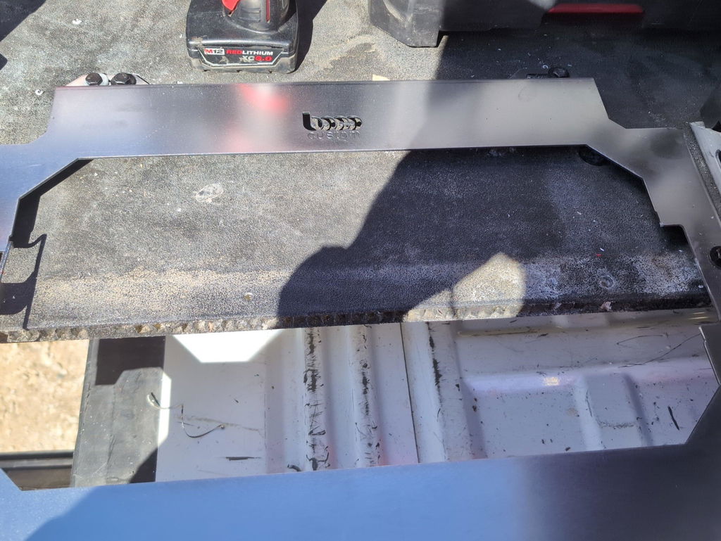
Illustration for Master Advanced DXF Customization for Seamless Professional Tool System Integration
Start with fundamentals that prevent downstream errors:
Draw at 1:1 scale and lock units. Mismatched inch/mm files are a leading cause of scrap.
Use closed polylines for cut contours; convert splines to arcs for predictable toolpaths.
Remove duplicate or overlapping entities; purge hidden blocks and construction lines.
Assign consistent layers: Profile, Inside Cut, Etch/Mark, and Bend Lines (if applicable).
Place the origin at a usable datum, typically a lower-left corner for easy fixturing.
Account for the process you’ll use:
Laser: Apply kerf compensation via CAM or offset in CAD; add micro-tabs on small parts to prevent tip-up; set pierce points away from cosmetic edges.
Waterjet: Increase internal fillet radii to reduce dwell marks; avoid needle-nose features that trap garnet.
Plasma: Favor larger features and generous radii; expect a bigger kerf and taper—design for clearance over precision fits.
Router: Match inside corner radii to the cutter; dogbone or T-bone internal corners where rectangular hardware must fit.
Design for fit and finish:
Holes for bolts: add clearance (e.g., +0.010–0.020 in for laser) depending on material and process tolerance.
Slots: consider coating thickness; powder coat can add 0.003–0.006 in per side, impacting sliding fits.
Edges: break sharp corners with small chamfers/fillets to reduce snagging and improve powder adhesion.
Marking: put bend notes, center marks, or part numbers on a separate etch layer for easy sorting.
For tool storage customization and custom tool organization, align features with manufacturer patterns and accessories. When creating DIY tool mounting plates, use:
Repeatable hole patterns built as CAD blocks so you can reconfigure spacing across drawer widths.
Parametric constraints for plate width, slot length, and standoff positions to support multiple systems without redrawing.
Test coupons (e.g., a small strip with incremented slot widths) to dial in real-world kerf and coating buildup before running full plates.
Quality-check your fabrication DXF designs before export:
Validate closed loops and direction (inside vs. outside). Many CAM tools use layer or color to assign cut order and compensation—document your scheme.
Sequence cuts: mark small internal features for first cuts, outer profiles last.
Save to a widely compatible DXF version (R12–R14) to avoid spline and text issues across CAM packages.
If you’d rather skip setup and go straight to cutting, ready-to-use precision cutting files can save hours. Professionally prepared DXFs for heavy-duty, low-profile mounting plates ensure secure, repeatable results and integrate cleanly with popular systems—ideal when time, consistency, and durability matter.
Benefits of Advanced Customization for Tools
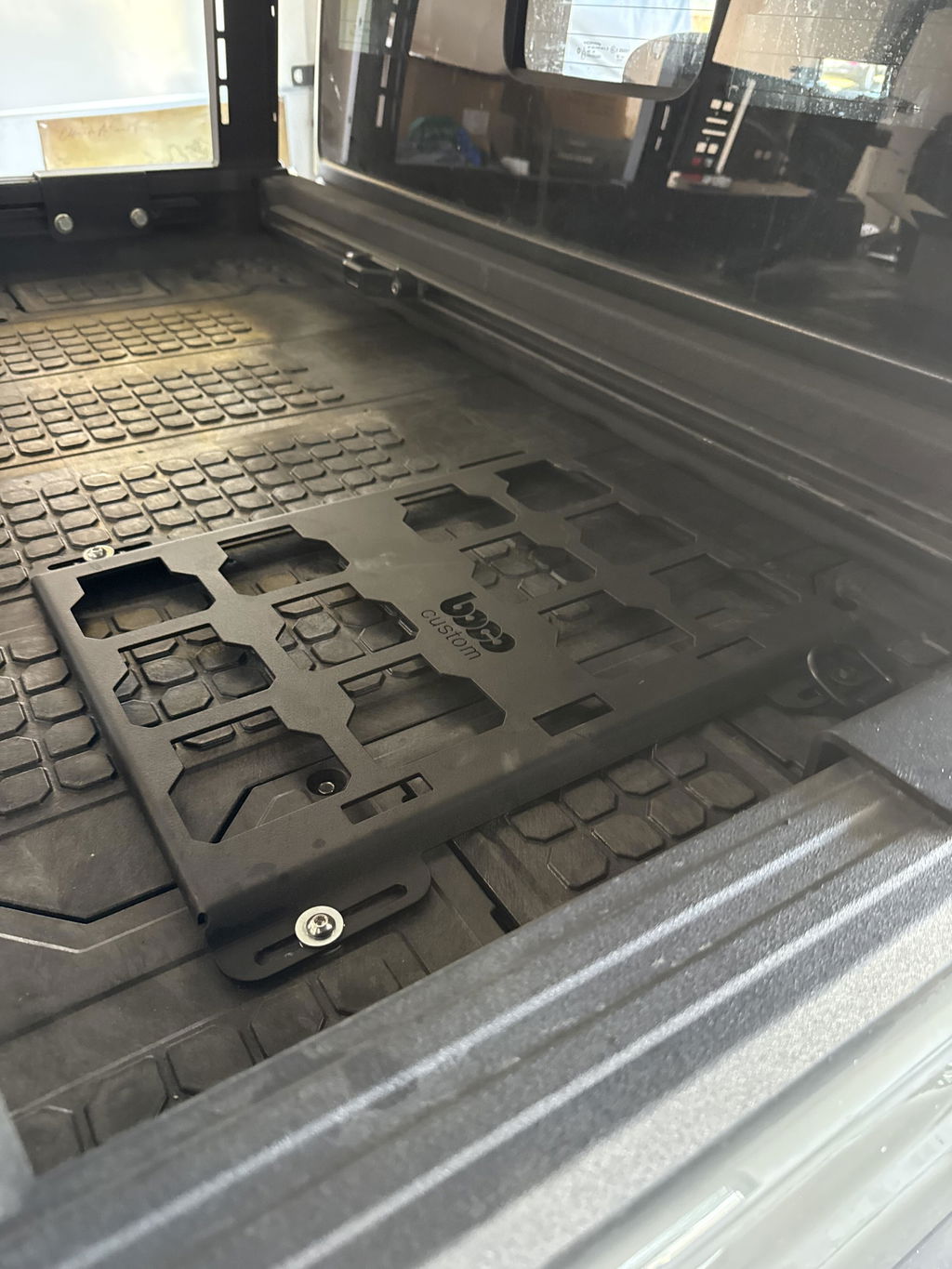
Advanced DXF file customization lets you tailor plates, brackets, and inserts to your exact workflow instead of forcing tools to fit a generic layout. For professionals who rely on major systems like Milwaukee Packout, that means clean fitment, faster access on-site, and less movement in transit.
Precision fit is the first win. By matching hole patterns, latch clearances, and handle reliefs to the actual interfaces on your boxes and drawers, components lock down without shims or guesswork. When each charger, nailer, or battery dock has a defined location, custom tool organization becomes predictable—and repeatable across multiple cases and crews.
It also compresses setup time. Dedicated cutouts, cable pass-throughs, and tie-down points let you stage tools powered and ready. Example: a low-profile plate for a 3-drawer unit with countersunk fasteners, etched cable channels, and slotted mounts for dual chargers prevents cable snags and keeps lids closing flush.
Typical elements you can dial in through DXF:
Mounting hole patterns for rivnuts, T-nuts, and threaded inserts (e.g., M6 or 1/4-20)
Slot widths and edge offsets tuned to material thickness and coating
Weight-relief geometry to reduce mass while preserving stiffness
Charger and accessory footprints with standoff spacers and ventilation
Label windows, engraved text, and QR codes via separate etch layers
Tie-down, cleat, and latch-clearance cutouts for reliable transport
Bend lines, bend radii, and notch reliefs for press brake operations
Kerf, lead-ins, and tabbing prepared for your CNC’s process
For fabricators, starting from well-structured fabrication DXF designs reduces scrap and rework. Layered precision cutting files—separating CUT, ETCH, and BEND—streamline programming regardless of whether you’re on laser, plasma, or waterjet. Proper lead-in placement and pierce avoidance protect small features, while bend allowance notes keep folded parts on spec. The result: quicker first-article approval and fewer “second passes” on the table.
Material and finish choices become strategic. Steel for maximum rigidity, aluminum when weight matters, and stainless for corrosion resistance can be swapped with minimal drawing edits. Accounting for powder-coat build in slot and hole tolerances ensures hardware still seats cleanly after finishing—critical for low-profile, flush-mounted hardware on tool storage customization projects.
Consistency at scale is another benefit. Once a layout is validated, you can replicate it for every truck, gang box, or technician. Teams can share DIY tool mounting plates and iterate fast, maintaining a common standard while adapting to specialty tools.
Whether you download ready-to-cut files or order finished, powder-coated plates, this approach turns your storage into a locked-in system—fewer rattles, faster pulls, and a setup that supports productivity day after day.
Key Considerations for Quality DXF Designs
Start with the functional interface. For a plate that mates to a professional tool system, define the exact engagement points, clearances, and load paths before drawing anything. Identify latch slots, keyholes, and fastener locations as datums, then build the rest of the geometry from those references. This prevents drift when you iterate on accessory patterns or handle different case sizes in the same model.
Set up the file correctly. Advanced DXF file customization benefits from disciplined structure:
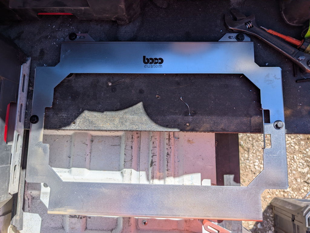
Illustration for Master Advanced DXF Customization for Seamless Professional Tool System Integration
Units: lock to inches or millimeters and note it in a non-cut layer.
Origin: place 0,0 at a consistent corner; keep all geometry at Z=0.
Layers: separate CUT_OUTER, CUT_INNER, ETCH/MARK, COUNTERSINK, TAPPED, and BEND lines. Many shops also want LEAD_IN tabs flagged on their own layer.
Entities: convert splines and text to polylines; use arcs, not bezier curves; remove duplicates and tiny fragments; ensure closed contours.
Design for the cutting process. Precision cutting files must anticipate kerf, heat, and taper:
Laser: kerf ~0.006–0.015 in (0.15–0.38 mm). Minimum hole ≈ material thickness; better at 1.2× thickness.
Waterjet: kerf ~0.030–0.040 in (0.76–1.02 mm) with slight taper; avoid micro-features under 0.060 in (1.5 mm).
Plasma: keep holes ≥1.5× thickness; avoid small interior radii.
Plan fit and fasteners with realistic tolerances:
Clearance holes: 1/4-20 = 0.266–0.272 in; M6 = 6.6–7.0 mm. Slot clearance for sliding features: +0.010–0.020 in over hardware size for laser; +0.030–0.040 in for waterjet.
Countersinks: call out angle (82° imperial, 90° metric) and depth; place on a dedicated layer. For low-profile designs, countersink so heads sit 0.005–0.010 in below the surface before powder coat.
Account for finishing and durability. Powder coat typically adds 0.002–0.004 in (50–100 μm) per side. Increase sliding or latch clearances by 0.010–0.015 in total to prevent binding. Add small chamfers or 0.010–0.020 in corner breaks to reduce sharp edges without secondary ops.
Use reliefs and joinery that assemble cleanly:
Dogbone or T-relief in interior 90° corners where square hardware or inserts must seat.
Bend relief and notes if a bracket accompanies the plate; specify bend radii as 1× material thickness for 5052-H32 aluminum or 1–1.5× for mild steel.
Include production-friendly details:
Microtabs: 0.060–0.120 in wide on outer profiles to keep parts in the sheet; mark them on a tab layer.
Etch-only layers for part numbers, center marks, and “no coat” zones if grounding is required.
Nesting margins: keep 0.100–0.200 in between parts for laser; more for waterjet.
Validate with a test coupon. Export a small section of the interface—such as a latch slot array or fastener cluster—and cut in the target material to confirm tolerances. This step saves time for DIY tool mounting plates and scales reliably across fabrication DXF designs used for custom tool organization and tool storage customization.
Well-structured advanced DXF file customization yields repeatable, shop-ready files and faster turnaround, whether you’re delivering a one-off prototype or a full run of precision cutting files.
DIY Fabrication for Professional Tradespeople
Building your own mounting solutions starts with accurate, editable files and a workflow that anticipates real-world use. With advanced DXF file customization, you can tailor fabrication DXF designs to match your exact tool system, vehicle, and workload while maintaining production-grade fit and finish.
Start with a proven baseline. Using precision cutting files designed for popular modular tool systems gives you correct footprints and latch clearances from the outset. From there, adjust the geometry to your setup instead of redrawing from scratch.
Practical customization moves to consider:
Material and thickness: For DIY tool mounting plates, 10–11 gauge steel (0.120–0.135 in) balances stiffness and weight. For corrosion resistance and easier handling, 5052-H32 aluminum at 0.125 in is a strong choice; add flanges or gussets if you expect heavy dynamic loads.
Kerf and process allowance: Laser kerf typically ranges 0.006–0.010 in; CNC plasma can be 0.030–0.050 in. Oversize holes and slots by the expected kerf plus 0.003–0.010 in depending on fit. Router-cut aluminum with a 0.125 in end mill needs dog-bone fillets in internal corners to seat square hardware.
Coating impact: Powder coat builds about 0.002–0.006 in per side. Loosen fits for mating features and hardware accordingly. Add hanging holes and mask zones for electrical bonding or grounding.
Hole strategies: For 1/4-20 hardware, a 0.266–0.272 in clearance hole is typical pre-coat; for M6, 6.6–6.8 mm. Use countersinks at 82° for imperial and 90° for metric fasteners; label the angle and depth on an ETCH layer.
Edge distances: Keep holes at least 1.5× material thickness from edges to reduce tear-out under vibration. Slot orientation should keep load paths aligned with bends or ribs.
Threaded inserts: Plan for self-clinching nuts or studs. Follow the insert manufacturer’s hole sizes and minimum sheet thickness, and add relief notches if needed near edges or bends.
Set up your DXF for fabrication clarity:
Layers: CUT for through-cuts, ETCH for text and logos, BEND for bend lines, and MARK for drill/tap centers. Color-code for quick checks at the machine.
Units and version: Lock units in the title block and save to a shop-friendly DXF flavor (R12 or 2018 are widely supported). Confirm that polylines are closed and free of duplicates.
Tabs and lead-ins: Add micro-tabs on long, narrow features to prevent tip-up. Place lead-ins outside critical edges to preserve hole roundness.
Optimize for your system and space:
Nesting: Rotate and mirror non-symmetric brackets to reduce scrap. Keep grain-conscious parts aligned if you’ll form flanges.
Mounting patterns: Create a parametric sketch for common rack hole grids and cargo track spacing. Suppress or expose features to suit vans, trailers, or wall panels.
Identification: Etch part numbers, bend directions, and hardware callouts to speed assembly and future reorders—valuable for custom tool organization at scale.
Using ready-to-cut files as a backbone lets you focus on tool storage customization rather than trial-and-error geometry. Whether you’re fabricating single plates or a full system, disciplined DXF practices translate into faster cutting, cleaner assembly, and long-term durability on the job.
Integrating Custom Solutions with Existing Systems
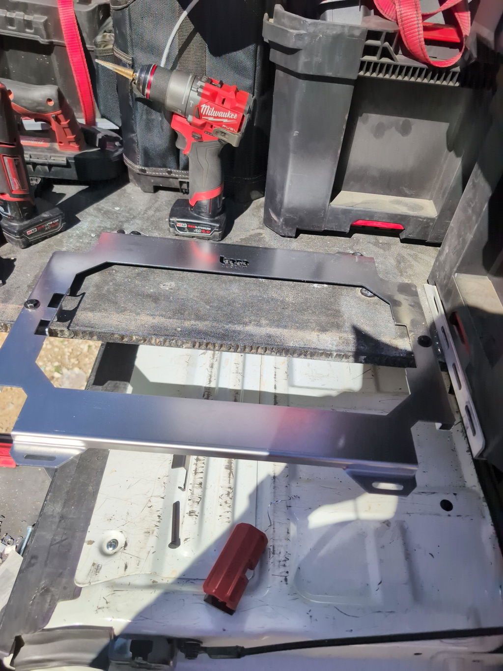
Integrating custom brackets, trays, and mounts into established tool ecosystems starts with the interface. With advanced DXF file customization, you can keep the OEM latch or bolt pattern intact while tailoring the top layout for your workflow. This approach preserves compatibility with systems like Milwaukee Packout and similar professional platforms while enabling true custom tool organization.
Begin by reverse-engineering the attachment geometry with care. Establish datums on the OEM plate or box (centerline and a primary edge), then capture hole centers, slot widths, latch envelopes, and any keep-out zones with calipers or a coordinate measuring routine. Build these into your CAD model as constrained sketches and export precision cutting files when ready.
Key techniques that streamline integration:
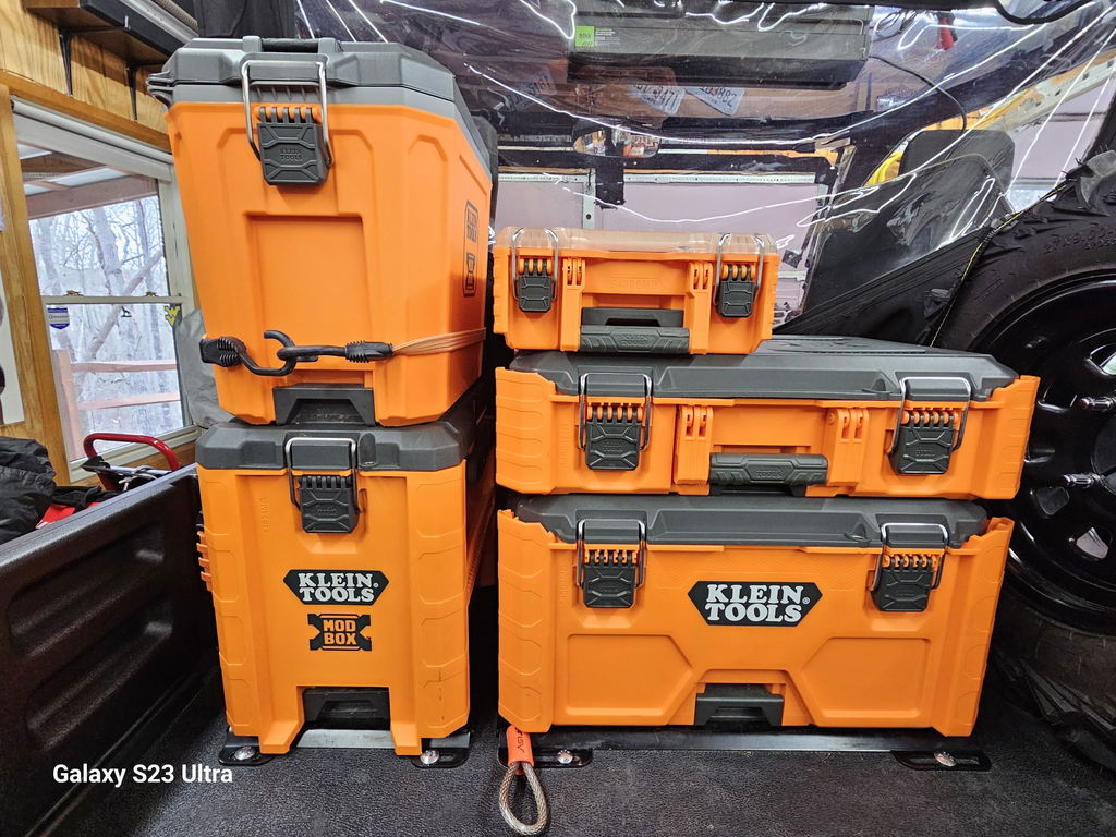
Illustration for Master Advanced DXF Customization for Seamless Professional Tool System Integration
Preserve the mounting footprint: Lock in the factory bolt pattern or latch pockets as a protected block you don’t edit. Adjust only the accessory side of the design.
Add adjustability: Use elongated slots (length aligned to expected tolerance direction) to accommodate small misalignments across different toolboxes or generation updates.
Respect clearances: Model keep-out volumes for latches, release tabs, hinges, and handles. Add 0.5–1.0 mm clearance to avoid interference, more if powder coating will be applied.
Apply kerf and process allowances: Set minimum inside radii to at least the tool’s kerf. For laser, very tight radii are feasible; for waterjet or plasma, increase fillets to avoid heat-affected distortion and sharp stress risers.
Hardware planning: Choose common shop standards like 1/4-20 or M6 for rivet nuts and bolts. Provide adequate hole sizes and include test coupons in your fabrication DXF designs to validate fit before cutting the full plate.
Surface stackups: If powder coating, open holes and slots slightly to offset 50–100 µm per side. Countersinks should be modeled deeper to keep heads flush in a low-profile layout.
For load-bearing confidence, place mounting points near structural ribs or boxed sections, and distribute weight to avoid cantilevered stress. Use filleted transitions around cutouts for impact resistance in transit. Add vibration-damping pads or rubber isolators beneath high-frequency tools like grinders to protect fasteners and contents.
Layer discipline in your DXF accelerates shop throughput:
CUT layer: through-cuts only, with consistent color/lineweight.
ETCH/MARK: center marks, labels, bend notes, logo outlines.
BEND (if post-processed): dashed lines with angle callouts, even if the initial plate is flat.
TABS: micro-tabs for small parts to prevent tip-ups on laser tables.
Practical example: Start with a proven Boco Custom plate footprint for a major tool system. Keep the OEM interface locked, then add a modular grid of slots for chargers, battery docks, and bit rails. Integrate 1/4-20 rivet nuts along edges for future accessories. Countersink the plate face so fasteners sit flush, preserving the low-profile requirement inside drawers or beneath stackable cases.
If you prefer to fabricate in-house, Boco Custom’s instant-download DXF files provide accurate interfaces you can extend for DIY tool mounting plates. If you need a finished solution fast, opt for powder-coated, heavy-duty plates with same-day shipping and local pickup, then layer on tool storage customization using auxiliary brackets or signs made from your own precision cutting files.
Ensuring Secure and Organized Tool Transport
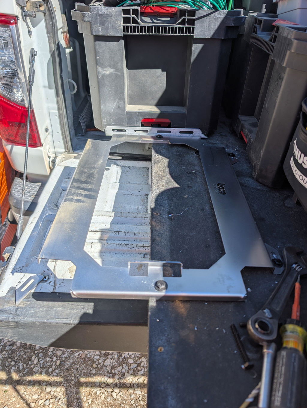
Secure transport starts with geometry you can trust. Advanced DXF file customization lets you tailor mounting plates to the exact tool system, vehicle, and load case, so nothing rattles loose, shifts under braking, or eats up valuable space.
Begin with proven fabrication DXF designs as your baseline, then refine the details for your setup. Whether you’re integrating with Milwaukee Packout rails, van racking, or shop carts, lock down these essentials:
Mounting pattern fidelity: Keep true positions to the OEM grid. Add 0.2–0.5 mm clearance on through-holes to account for laser kerf and powder-coat build. For M6 clearance, use 6.6–7.0 mm; for 1/4-20, 6.8–7.1 mm when coating is planned.
Slot strategy: Use elongated holes where alignment during install is likely. Orient slots in the direction of expected vibration to relieve shear on fasteners.
Edge distances: Maintain at least 2× hole diameter from edges to prevent tear-out during shock loading.
Material and thickness: Match plate thickness to load. Heavier items on low-profile plates benefit from 3–4 mm steel; light organizers are fine on 2–2.5 mm. Confirm minimum feature size for your process (laser: slot width ≥ material thickness + 0.2 mm).
Powder-coat allowances: Typical build is 50–100 μm per side. Add clearance to mating tabs and tight pockets so parts still fit after coating.
Tie-down and safety points: Integrate dedicated lashing holes or D-ring locations to belt in high-mass tools and cases.
Hand and cable clearance: Add reliefs for handles, latches, and charging cords so tools dock without binding.
Leverage layers in your precision cutting files to drive consistent outcomes:
CUT layer for through-profiles.
ETCH/MARK layer for labels, alignment targets, and QR codes for inventory.
Optional BEND layer if the design includes formed brackets (include bend radii and direction notes in a README).
For custom tool organization, incorporate visual cues that speed kitting:
Etch outlines or text for tool silhouettes, battery size, and torque class.
Add index numbers that mirror bin locations in your van or cart.
Use keyhole features for quick-release brackets so frequently used tools lift off without tools.
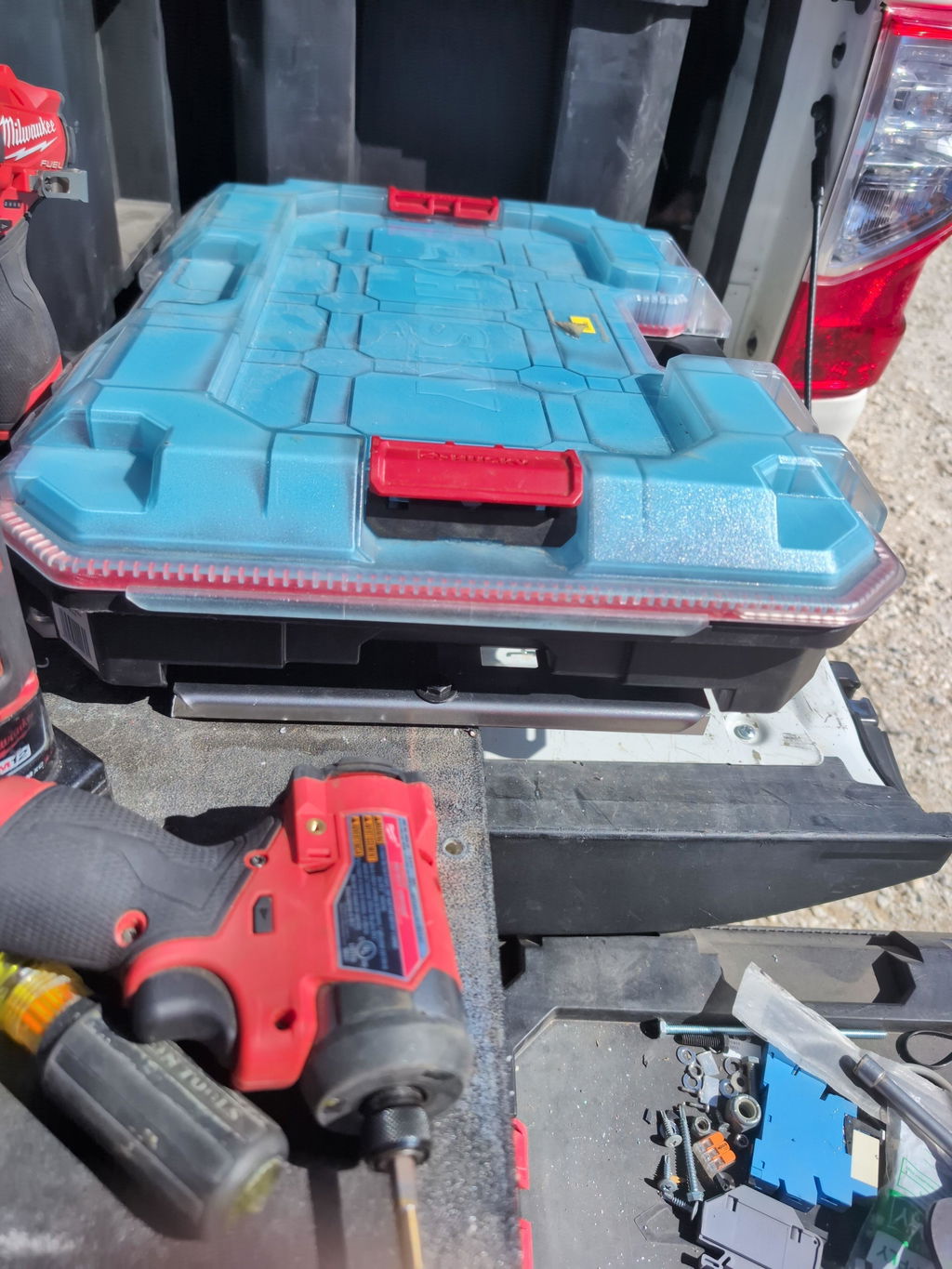
Example: A service van plate for Packout. Start from a BocoCustom plate DXF, add an M6 rivnut pattern that matches your van’s ribs, rotate the grid 90° so cases lock along the vehicle’s travel, include two 8 mm tie-downs per case, and add small drainage slots near the floor edge. Etch a grid reference and your asset IDs for faster audits.
Before cutting, validate:
Print a 1:1 paper template and test-fit on the vehicle wall or drawer.
Cut a small coupon with your tightest slot and hole stack-up to verify fit.
Confirm CAM kerf compensation aligns with your drawing (many shops expect “true size” geometry).
Whether you’re fabricating DIY tool mounting plates or ordering powder-coated hardware, disciplined tool storage customization comes from precise drawings. Instant-download DXF files accelerate iteration, while advanced DXF file customization ensures your final plate delivers secure, organized transport with no surprises.
Future Trends in Custom Tooling Solutions
Professional tool workflows are moving toward file-first pipelines where a configurable design becomes a finished part with minimal handoff. The next wave centers on advanced DXF file customization that encodes intent, not just geometry, streamlining everything from quoting and nesting to finishing and installation. For trades using PACKOUT-style systems, this translates into faster, cleaner, and more secure outcomes in the shop and on the jobsite.
Key developments shaping the next few years:
Parametric configurators for major systems: Expect on-demand fabrication DXF designs that let you select base system (Milwaukee PACKOUT, DeWalt TSTAK, Festool Systainer), plate thickness, fastener type, and edge offsets. Hole patterns, slot arrays, and tie-down points adjust automatically, enabling precise tool storage customization for carts, vans, and shop walls.
Layered “smart DXF” standards: Precision cutting files will increasingly embed layer conventions for cut, etch/engrave, bend, tap, and countersink. Engraved QR codes can link to torque specs, load ratings, or install videos. Dedicated note layers can call out hardware kits, powder-coat colors, and kerf allowances, reducing shop errors and rework.
CAM automation and nesting intelligence: AI-assisted nesting and machine-aware toolpaths will optimize yield and cycle time while placing tabs, corner reliefs, and micro-joints where they ease downstream finishing. Expect automatic pierce reduction for thicker gauges and improved small-feature protection for fiber laser and waterjet. This benefits both in-house teams and distributed job shops.
Hybrid mounting ecosystems: DIY tool mounting plates will pair heavy-duty steel or aluminum bases with 3D-printed inserts for tool-specific cradles, wire managers, and label frames. Metal provides strength and vibration resistance; printable components deliver quick, low-cost customization and easy updates as tool collections evolve.
Built-in structural validation: Load paths, duty ratings, and fastener pull-out data will be baked into design notes or etch layers. For rugged, low-profile setups that ride in service trucks, finite-element checks and real-world test fixtures help ensure repeatable performance under vibration and impact.
Faster fulfillment choices: Pros will mix instant-download DXF files for in-house cutting with same-day shipping of powder-coated plates when speed is critical. Local pickup remains valuable for urgent installs and color-matched batches for custom tool organization across crews.
Interoperability and revision control: Versioned files—clearly tagged with material, finish, and rev history—will sync with BOMs and work orders. Shops can track as-built changes, then push improvements back into the master DXF so future runs are cleaner and faster.
Boco Custom is aligning with these directions by delivering durable, low-profile mounting solutions and precision cutting files that support real-world fabrication. Whether you need ready-to-install plates or downloadable designs to run on your own equipment, advanced DXF file customization will continue to compress lead times and elevate the quality of every install.
Standard shipping takes 5 to 7 business days. Express (2 to 3 days) and overnight options are available at checkout. Orders over $50 ship free.
Can I order online and pick up in store?
Yes. Select "Pick up in store" at checkout and choose your nearest location. Most orders are ready within 2 hours.
What if my order arrives damaged?
Contact us within 7 days of delivery with your order number and a photo. We'll arrange a replacement or refund, no return shipping required.
AI-Generated Content Disclosure
This blog post was created with the assistance of RankGPT, an AI-powered tool designed to generate high-quality, SEO-optimized content at scale.
As a small business embracing modern technology, we use AI to help us:
Produce informative articles more efficiently
Increase our online visibility through better performance in traditional search engines (like Google) as well as emerging AI-powered searches and answer engines
Reach more potential customers and grow our presence in a competitive digital landscape
By leveraging tools like RankGPT, we're able to publish valuable content more consistently and scale our efforts in ways that would otherwise take significantly more time and resources.
Important notes for readers:
While RankGPT helps create well-structured and relevant content based on current best practices, AI-generated posts are not always 100% accurate, complete, or free from errors.
The information, opinions, and perspectives expressed may not fully reflect the exact views, experiences, or official positions of Boco Custom, its team members, or the individuals involved in our business.
AI content should be viewed as a starting point or general resource—not as personalized professional advice, definitive facts, or a substitute for direct consultation with us or qualified experts.
We always recommend verifying important details independently, especially for decisions related to custom products, services, or any business matters.
We are committed to transparency and continually work to improve our content. If you have questions, feedback, or spot any inaccuracies, please reach out—we genuinely appreciate it!
Not only is this way overbuilt for the price with its solid, confident craftsmanship, I am completely convinced that these guys are the best around when it comes to the packout platform.
I like these, they are much more compact than what Milwaukee offers. I had them powder coated in silver vain and they look awesome. I love the bonus half rack they sent me. That’s the mark of a nice company.


Dejar un comentario