Mastering DXF File Optimization for Flawless Plasma, Laser, and CNC Cutting
Introduction to DXF File Optimization
DXF is the handoff between your CAD intent and the CAM toolpath that hits metal. Clean geometry, consistent units, and process-aware details are what separate smooth runs from costly rework. Optimizing DXF files cutting workflows starts with how you draw, organize, and export.
Focus on geometry quality:
Work in 1:1 scale and lock units (in or mm). Don’t mix.
Convert splines and ellipses to arcs/polylines with tight fit tolerances. Avoid micro-segmentation.
Join open contours. Inside features must be closed so CAM knows cut direction.
Remove duplicates, overlaps, and zero-length entities; they cause double cuts and dwell.
Explode blocks and convert live text to outlines when you intend to cut it.
Use layers with intent:
Separate cut, etch/mark, and bend lines by layer and color. Name them clearly.
Keep kerf compensation out of the DXF; apply it in CAM for the target machine.
Design to the process:
Plasma cutting DXF preparation: Plan lead-ins/outs away from small features. Pierce clearance matters. As a rule of thumb, keep hole diameters ≥ 1.2–1.5× material thickness for round results, and maintain webs ≥ material thickness to control heat. Add micro-tabs to prevent tip-ups during long runs.
Laser cutting DXF best practices: Favor true arcs over tiny segments for fast, smooth motion. You can push smaller radii and finer slots, but still tab long, narrow parts. Consider common-line cutting only when heat input and sequencing won’t distort.
CNC routers: Size internal corners with dog-bone or T-bone relief to fit square hardware. Constrain minimum internal features to tool diameter + clearance. Add hold-down tabs; consider onion-skin passes on thin sheet.
Tighten fit and finish:
Account for coating and finishing. If a bracket will be powder-coated, widen slots and holes accordingly.
For assemblies, add datum holes for fixture repeatability and consistent alignment.
Use material-aware minimums. Thin stainless behaves differently than mild steel; adjust pierce points and sequencing.
These CNC cutting DXF tips and CAD file optimization techniques drive DXF file precision fabrication. At Boco Custom, our instant-download DXFs for heavy-duty, low-profile mounting plates are exported with true arcs, joined paths, clean layers, and process-ready details so fabricators can cut with confidence on plasma, laser, or CNC.
Understanding CAD Export Settings
Export settings are the bridge between a clean CAD model and a file your CAM software can trust. Small choices here impact kerf compensation, cut order, and edge quality across plasma, laser, and CNC workflows. Use these CAD file optimization techniques to lock in predictable results.
Units and scale: Work 1:1 in inches or millimeters and export in the same units. Avoid “unitless” DXFs. Verify in your CAM import dialog that the size matches your print.
DXF version: Choose a widely compatible ASCII format such as R12 or 2000. Newer formats sometimes introduce entities legacy CAM tools don’t parse cleanly.
Geometry type: Prefer polylines with true arcs (bulge) over splines or NURBS. If your CAD uses splines, convert to polylines with arcs before export. Keep lineweight at 0 and linetype “Continuous.”
2D flattening: Project to 2D, set Z = 0 for all entities, and remove hidden 3D edges. Explode blocks and external references so your CAM sees discrete contours.
Closed, non-overlapping paths: All outer profiles and holes must be closed loops with no gaps or duplicates. Use commands like Overkill/Join and set a join tolerance that’s smaller than your kerf (e.g., 0.001–0.003 in / 0.025–0.075 mm).
Tolerances and chord error:
- Laser cutting DXF best practices: chord height 0.0005–0.002 in (0.012–0.05 mm).
- CNC routers: 0.001–0.005 in (0.025–0.125 mm).
- Plasma cutting DXF preparation: 0.003–0.010 in (0.075–0.25 mm).
Preserve arcs instead of over-segmenting; fewer nodes means smoother motion.
Layer strategy: Separate operations with clear layer names and colors:
- CUT_OUTSIDE: exterior profiles
- CUT_INSIDE: holes/slots
- ETCH/MARK: surface marks
Keep only what you need—purge construction geometry and dimensions.
Origin and sheet placement: Move the part or nested layout so the lower-left corner sits near 0,0 with positive coordinates. This simplifies fixturing and CAM nesting.
Text and logos: For cut-through letters or engraving, convert text to outlines. Use single-line fonts for scribe layers to minimize cycle time.
Tabs, lead-ins, and kerf: Do not “bake in” tabs or kerf offsets in the DXF. Provide nominal geometry; apply kerf compensation, tabbing, and lead-ins in CAM to match the actual tool and material.
Following these CNC cutting DXF tips helps ensure DXF file precision fabrication and reduces CAM cleanup. At Boco Custom, our instant-download files follow these conventions, optimizing DXF files cutting workflows for plasma, laser, and CNC without surprises.
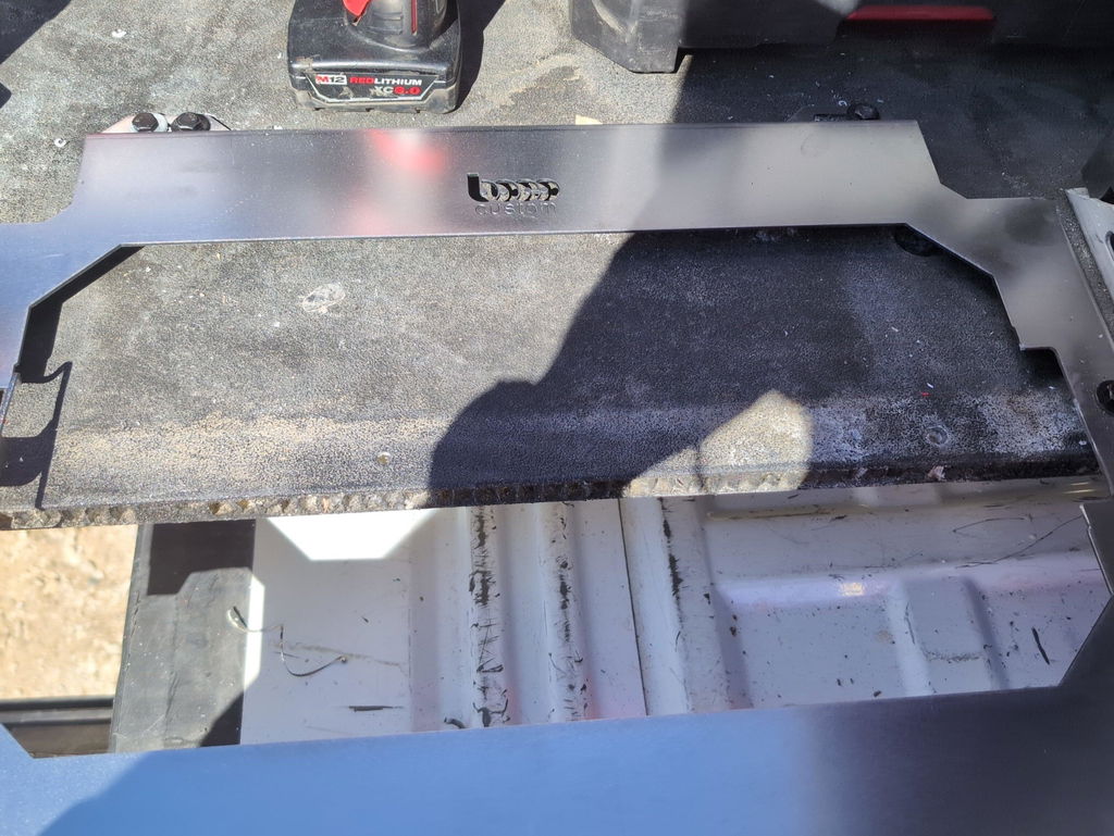
Illustration for Mastering DXF File Optimization for Flawless Plasma, Laser, and CNC Cutting
Common DXF File Preparation Errors
Even experienced fabricators lose time to avoidable DXF mistakes. Most issues trace back to drawing hygiene and export settings, not the machine. When optimizing DXF files cutting on plasma, laser, or router machines, watch for these pitfalls:
Units and scale mismatches: Designing in millimeters and exporting as inches (or vice versa) silently scales parts by 25.4. A 6 mm slot becomes 0.236 in. Confirm units on export and in CAM; include a known test feature (e.g., a 100 mm square) to validate.
Open contours and tiny gaps: CAM won’t recognize open profiles as cut paths, especially for holes. Gaps as small as 0.001 in cause problems. Use Join/Extend, set a reasonable fuzz distance, and verify loops are Closed polylines.
Duplicate and overlapping geometry: Stacked lines trigger double cuts and heavy dross. Run Overkill/Remove Duplicates and use a single, continuous path per contour.
Splines and excessive nodes: Splines or micro-segmented curves make choppy toolpaths. Convert to arcs/polylines with a tolerance that preserves shape but reduces node count. Aim for smooth arcs on radii.
Non-zero Z and 3D artifacts: Entities at varying Z won’t process correctly. Flatten all geometry to Z=0 before export.
Blocks, xrefs, and un-exploded symbols: Nested blocks hide bad geometry and layer conflicts. Explode, purge unused definitions, and simplify before CAM import.
Layer misuse and unconverted text: Mixing cut/etch/scribe on one layer or leaving TrueType text un-outlined causes missing features. Use clear layers (CUT, ETCH, MARK), and convert text to polylines.
Undersized features vs process limits: If slot width < kerf/beam, it won’t resolve. Typical plasma kerf is ~0.060–0.090 in; lasers can be ~0.004–0.012 in. Ensure pierce-to-edge distance and hole diameters exceed minimums; add tabs where necessary.
Inside/outside detection and lead-ins: Wrong loop orientation or islands confuse CAM. Ensure inner loops (holes) are separate, set sensible lead-ins/outs, and avoid leading into sharp corners. These are core plasma cutting DXF preparation and laser cutting DXF best practices.
Router-specific corners: For CNC routing, add dogbone/teardrop fillets to internal corners so square hardware fits.
Stray points and far-off extents: Tiny specks far from the part stretch drawing extents, causing long machine rapids. Purge, delete construction lines, and move the part near 0,0.
Inconsistent tolerances: Overly tight decimals inflate file size and jittery moves. Use practical precision based on process capability.
Apply these CAD file optimization techniques as a preflight checklist for DXF file precision fabrication. If you need clean starting points, pre-vetted downloads from trusted providers like Boco Custom reduce rework and speed CAM setup—solid CNC cutting DXF tips you’ll feel on the shop floor.
Ensuring Geometric Accuracy and Scale
Start with units and scale. Always draw 1:1 and confirm the target unit system before export. Because DXF files don’t reliably embed units, verify after import into CAM that 1 unit equals 1.0 mm or 1.0 in as intended. Add a 25 mm or 1 in calibration square to the file; if the CAM reads that square correctly, your scale is right. This simple step is foundational for optimizing DXF files cutting across different machines and shops.
Clean geometry prevents bad toolpaths. Use CAD file optimization techniques before export:
Join open segments into closed polylines; no gaps, no overlaps.
Remove duplicates and zero-length entities (e.g., “OVERKILL” in AutoCAD).
Flatten to Z=0; purge blocks, hatches, and stray construction lines.
Convert text to outlines; use single-line fonts for scribe/etch operations.
Replace splines with arc-fit polylines at a small chordal deviation (e.g., 0.05–0.2 mm or 0.002–0.008 in) to keep curves smooth but efficient.
Check feature sizes against real hardware. For DXF file precision fabrication, specify hole and slot sizes with proper clearance:
Fasteners: M8 clearance 8.5–9.0 mm; 1/4-20 clearance 6.8–7.0 mm.
Slots: include radius at ends equal to or greater than tool radius.
Inside corners: add fillets or dogbones so flat tools can reach; minimum inside radius ≥ endmill radius.
Account for process-specific realities:
Plasma cutting DXF preparation: anticipate kerf of ~0.8–1.5 mm. Very small holes (≈ material thickness or smaller) may wash out; pierce leads should avoid critical features.
Laser cutting DXF best practices: kerf is small (~0.05–0.3 mm) but varies by lens and material; keep tiny bridges and tabs robust enough to survive heat.
Router/CNC: minimum slot width ≥ tool diameter; consider onion-skin passes or tabs in CAM, but ensure there’s room in the DXF to place them away from precision edges.
Adopt these CNC cutting DXF tips for reliable imports:
Separate layers: CUT, ETCH/SCRIBE, and REFERENCE.
Place the origin at a logical datum; align critical hole patterns to axes.
Keep lead-in space by offsetting critical edges when possible.
Before a full run, cut a small coupon with a critical hole pattern and compare with calipers. If the CAM or machine scales, flips, or offsets your trial, correct it at the source and re-export. This tight feedback loop is the fastest path to repeatable results.
Nesting Strategies for Material Efficiency
Smart nesting turns clean geometry into real savings—more parts per sheet, fewer pierces, shorter cycle times, and less heat distortion. Whether you’re running a fiber laser, plasma, or a router, the fundamentals are the same: control spacing, stabilize small parts, and plan the cut path. Here are CNC cutting DXF tips that consistently boost yield when optimizing DXF files cutting operations.
Use true‑shape nesting, not just rectangular bounding boxes. Curved parts often tuck together to unlock 3–8% more sheet utilization.
Respect process‑specific spacing. As a starting point: fiber laser 1–1.5x material thickness (often 1–2 mm or 0.040–0.080 in on thin sheet), plasma 2–3x thickness (3–6 mm or 0.125–0.250 in), router 1x tool diameter. Increase gaps around heat‑dense features (slots, hole clusters).
Account for lead‑ins/lead‑outs. Keep at least the lead‑in length plus kerf from adjacent parts; move lead‑ins to scrap whenever possible to protect finished edges.
Common‑line cut selectively. It’s excellent for laser and waterjet on consistent material; use caution on plasma where heat can pull edges. Avoid common‑lining near holes or thin webs.
Apply part‑in‑part nesting. Place small parts inside large internal cutouts when kerf and lead‑in clearance allow. Add microtabs to prevent tip‑ups.
Control heat flow. Stagger pierces, alternate sides, and avoid concentrating cuts in one zone. For plasma cutting DXF preparation, increase spacing around thick sections and schedule roughing passes before finish cuts on precision edges.
Honor grain and bend orientation. For brushed stainless or directional aluminum, lock rotation. Keep bend lines parallel across a nest to reduce springback variation.
Stabilize the skeleton. Leave bridges between parts and the sheet edge so the skeleton doesn’t collapse near the end of the run. Tab small parts (0.5–1.0 mm for laser; 1.5–3.0 mm for plasma) and orient tabs away from cosmetic faces.
Reserve clamp and nozzle clearances. Define dead zones for grippers or magnets; avoid placing pierces where clamps shadow the beam or torch.
Label intelligently. Use an etch/mark layer in your DXF for part numbers, orientation arrows, and grain marks so operators can sort quickly without re‑measuring.
Example: On 11‑ga (3 mm) mild steel, a tuned laser nest with 1.5 mm spacing, outside‑edge lead‑ins, and selective common‑line cutting typically yields 88–92% utilization on a 48×96 in sheet; plasma with 4–6 mm spacing usually nets 80–86% with improved stability.
For laser cutting DXF best practices and DXF file precision fabrication, keep geometry watertight, remove duplicates, and group parts by thickness and finish. These CAD file optimization techniques also make nesting software faster and more predictable. Boco Custom’s downloadable DXF files use clean contours and logical layers so you can apply these strategies immediately in your CAM.
Verifying Tool Paths and Kerf Compensation
Before sending a DXF to the torch, beam, or spindle, verify that the CAM tool paths reflect the geometry—and the cut width—you actually expect. Accurate kerf compensation is central to DXF file precision fabrication; a few thousandths off on inside features can stack up to real assembly headaches.
Start with quick geometry checks in your CAD/CAM:
Confirm units and scale (mm vs in). A 25.4x error ruins fit.
Convert entities to closed polylines; heal gaps smaller than your kerf.
Remove duplicate/overlapping lines; explode blocks if your CAM requires it.
Keep arcs as arcs (not tiny segments) to avoid choppy motion on lasers and routers.
Separate layers for cut, etch/mark, and bend lines to control toolpath strategies.
Apply process-appropriate CAM strategies:
Offsets and direction: Use inside compensation for holes/slots, outside for exterior profiles. Clockwise vs counterclockwise may matter on some controllers; verify the previewed offset is correct before posting code.
Lead-ins/outs:
- Plasma: arc or tangent leads, 0.15–0.25 in length at 30–60°, never at corners; lead out to avoid divots.
- Laser: very short leads (0.02–0.04 in) or on-edge pierce when part quality allows.
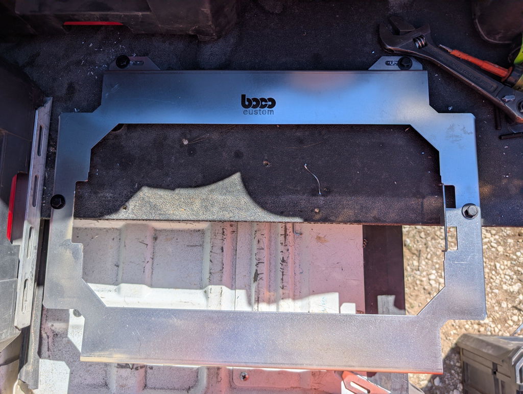
Illustration for Mastering DXF File Optimization for Flawless Plasma, Laser, and CNC Cutting
- Router: ramp or helical entries to protect edges and cutters.
Pierce/entry points: Place on scrap side, mid-edge, away from holes and tight corners.
Cut order: Small internal features first, then profiles. Add microtabs (0.06–0.12 in wide) every 6–12 in to prevent tip-up; remove in a secondary op.
Heat and movement: For plasma/laser cutting DXF preparation, sequence parts to spread heat, skip around large areas, and avoid back-to-back long cuts on the same edge.
Dial in kerf with test coupons, not assumptions:
Typical kerf values: fiber laser 0.004–0.012 in (0.10–0.30 mm), plasma 0.032–0.060 in (0.8–1.5 mm) depending on amperage/material, waterjet 0.015–0.040 in (0.38–1.0 mm), router equals cutter diameter.
Cut a 1.000 in square and measure the slug/slot to calculate actual kerf, then input that value in CAM. For example, if a plasma slot measures 0.940 in, kerf is ~0.060 in; set tool diameter accordingly.
Use practical, testable targets:
Need a 0.500 in bolt hole? Program a 0.520–0.530 in toolpath on plasma to account for kerf and clearance; laser may only need +0.004–0.008 in.
For router-cut pockets, add dogbone or T-bone fillets to internal corners so square hardware seats properly—classic CAD file optimization techniques.
Always simulate and backplot. Look for wrong-side offsets, start points in corners, uncut islands, and tool lifts that could scar the part. Keep the master DXF untouched; make kerf, leads, and cut order CAM-side. These CNC cutting DXF tips are foundational to optimizing DXF files cutting and align with laser cutting DXF best practices for consistent, first-article success.
Post-Processing and Export Guidelines
Lock in accuracy before you export. After modeling, run a 2D cleanup pass to make cut-ready geometry:
Flatten all entities to Z=0 and purge 3D features, hatches, dimensions, and construction lines.
Join segments into closed polylines; remove duplicates, overlaps, and zero-length entities (AutoCAD: OVERKILL + JOIN).
Replace splines with arcs/lines; many controllers ignore splines. Set a reasonable curve tolerance (e.g., 0.01–0.05 mm).
Verify consistent units. Label the file INCH or MM and ensure scale 1:1.
Organize layers to communicate process intent. Keep each cut type isolated and color-coded for CAM import:
OUTER_CUT (exterior profiles)
INNER_CUT (holes, pockets)
ETCH/MARK (logos, bend lines)
DRILL (features to be drilled, not cut)
Avoid kerf compensation in the DXF. Export nominal geometry and apply kerf, lead-ins/outs, and tabs in CAM. The exception is press-fit features where you intentionally offset for fit; document those offsets.
Account for machine-specific realities during post-processing:
Plasma cutting DXF preparation: Avoid holes smaller than 1.5x material thickness; pierce points need clearance from tiny features. For 3 mm steel on a 45A system (~1.2 mm kerf), make 4.5–5 mm minimum hole diameters; drill anything tighter.
Laser cutting DXF best practices: Maintain small segment lengths (>0.2 mm) to prevent controller slowdown; add micro-reliefs to sharp internal corners to reduce heat buildup on thick plate.
CNC routers: Add dogbone or T-bone fillets to internal 90° corners so rectangular hardware fits. Size the fillet to the cutter radius (e.g., 3.175 mm radius for a 1/4" tool).
Prepare text and logos for marking or cutting:
Use single-line fonts for scribe/etch.
Convert all text to polylines/outlines; remove self-intersections.
Ensure minimum bridge/letter thickness exceeds 2–3x kerf for cut-through signage.
Choose an export version that maximizes compatibility. DXF R12/R14 ASCII with polylines and arcs is a safe default for most controllers. Set high precision (at least 4 decimal places in inches, 3 in metric).
Set the origin thoughtfully. Place the lower-left of the part or sheet at 0,0 with positive coordinates only. This simplifies nesting and eliminates negative travel limits.
Before sending to the shop, run a final checklist: closed profiles only, layer naming consistent, no hidden duplicates, correct units, and notes for any special operations. For teams optimizing DXF files cutting across plasma, laser, and CNC, this discipline prevents scrap and preserves DXF file precision fabrication.
Boco Custom’s instant-download DXFs follow these CAD file optimization techniques so fabricators can load, nest, and cut with minimal adjustment—ideal for professional tradespeople who need reliable, repeatable results.
Troubleshooting Fabrication Issues
When parts don’t fit, edges look ragged, or holes run out of round, the root cause is often upstream in the CAD. Focus your troubleshooting on optimizing DXF files cutting before you tweak machine parameters.
Scale and units: A classic failure is inch/mm mismatches. Confirm your CAD units, then check a known dimension (e.g., overall plate width) against the bounding box in CAM. If a 200 mm part shows as 7.874 in, your scale is correct; if it appears as 200 in, rescale before toolpathing.
Open contours and duplicates: Plasma and laser frequently pause or overburn at gaps or overlapping lines. In CAD, join/close profiles, delete duplicates, and convert text to geometry. Most tools have an “overkill” or “optimize” command—run it, then verify path continuity in CAM.
Splines and excessive nodes: Complex splines explode into tiny segments that chatter the head and slow feeds. Convert splines to polylines with a reasonable chord height (e.g., 0.003–0.010 in for sheet work), and simplify nodes to reduce stutter.
Kerf compensation direction: Wrong-side offsets produce undersized outer profiles or oversized holes. Apply inside offsets on holes/slots and outside offsets on exterior contours. Confirm toolpath arrows and start points before posting.
Lead-ins/outs and tabs: Long leads can crash into nearby features; short leads can scar edges. For small holes, use minimal or no lead-in with a pierce-on-center routine where supported. Add micro-tabs on narrow parts to prevent tip-ups; make them easy to grind off.
Minimum feature sizes: Respect process limits.
- Plasma cutting DXF preparation: Keep minimum hole diameter roughly 1.2–1.5× material thickness; expect best results at ≥1.5×. Plan slot widths at kerf × 2 plus clearance.
- Laser cutting DXF best practices: Laser can hold smaller holes, but maintain at least 2× kerf width for slots to avoid heat buildup.
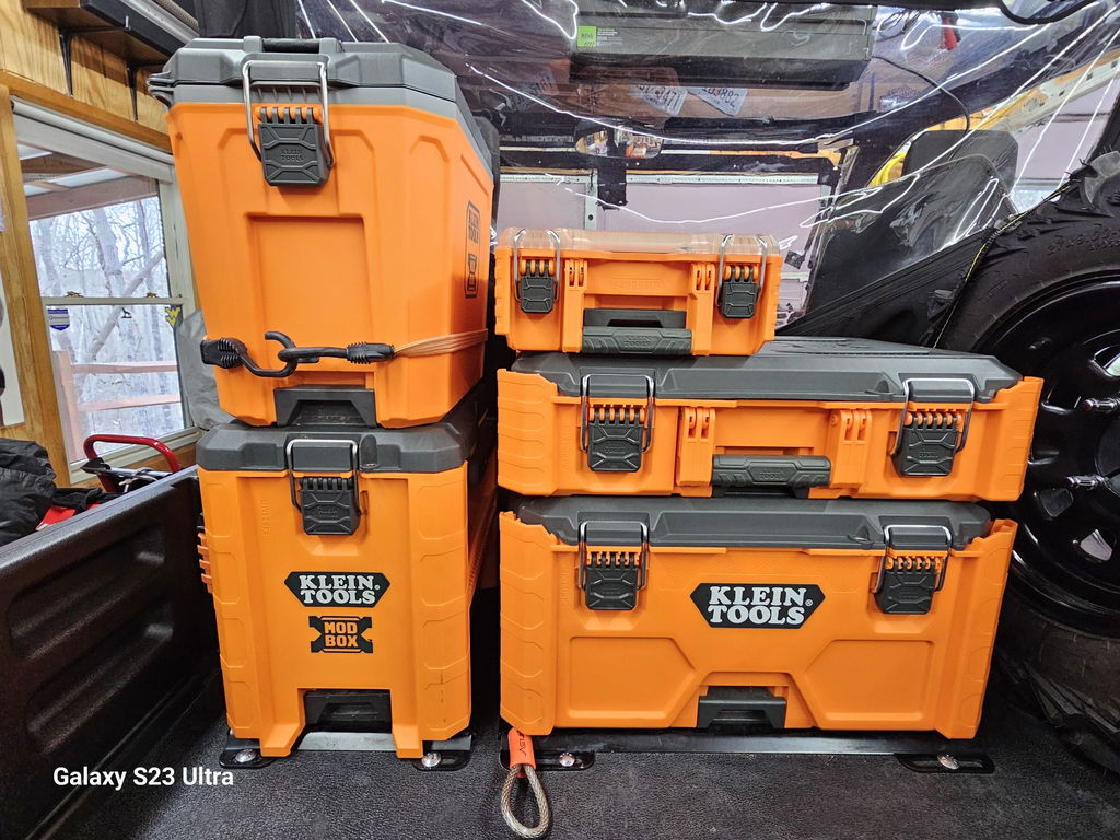
Illustration for Mastering DXF File Optimization for Flawless Plasma, Laser, and CNC Cutting
- CNC routing: Add dog-bone or T-bone fillets on inside corners for square-fitting hardware.
Heat management: Sequence cuts from inside to outside, alternate across the sheet, and segment very long cuts. Reduce pierce counts via common-line cutting or bridging where safe.
Fitment tuning: For DXF file precision fabrication, incorporate realistic clearances. Example: a 0.250 in bolt in a laser-cut hole may need 0.260–0.266 in; add 0.005–0.010 in extra if parts are powder-coated.
Origin and layers: Place geometry near 0,0 with a single cut layer and optional etch/mark layers clearly named. Many CAM errors stem from mixed layers or entities on frozen/locked layers.
Quick test: Cut a small coupon with a hole, slot, and external profile. Measure deviations, then adjust kerf value, lead parameters, and offsets. These CAD file optimization techniques—and practical CNC cutting DXF tips—eliminate most shop-floor surprises and shorten your path from DXF to done.
Benefits of Optimized DXF Files
Clean, well-structured DXF geometry pays off at the machine and on the bench. By optimizing DXF files cutting workflows, you get predictable toolpaths, accurate fitment, and less time spent repairing files or grinding edges after the fact.
Precision translates directly into part quality. Closed contours, unified units, and properly joined polylines drive tight tolerances—critical when a mounting plate must match a factory hole pattern or accept carriage bolts without rattle. That’s DXF file precision fabrication: holes that gauge correctly, slots that guide fasteners cleanly, and edges that need minimal post-processing before powder coat.
Key gains from thoughtful CAD file optimization techniques include:
Faster cycle times: Merge duplicate lines, convert tiny line segments to true arcs, and minimize pierce points. For plasma cutting DXF preparation, common-line cut adjacent parts when material and heat allow; place lead-ins on scrap or non-critical edges.
Better edges and geometry fidelity: For laser cutting DXF best practices, favor tangent arcs over micro-segmented curves to avoid jerky motion. Add small fillets to inside corners to prevent dross and corner blowout; for routers, use dogbones in blind slots so rectangular components seat fully.
Lower rework: Correct inside/outside compensation in the file prevents undersized holes or oversize profiles. Apply realistic kerf or tool diameter assumptions (for example, plasma kerf ~1.5–2.0 mm, router tool Ø specified on a layer). Maintain consistent slot widths that match hardware (e.g., 0.313–0.325 in for 5/16-in carriage bolts).
Longer consumable life and stable heat: Reduce arc starts, chain cuts where possible, and stagger lead-ins to spread heat. On routers, “onion-skin” thin finishing passes stabilize small parts. These CNC cutting DXF tips cut scrap and preserve nozzle, lens, and bit life.
Cross-machine compatibility: Use consistent units, a sensible origin, and layers for cut/mark/etch. That makes the same file reliable for plasma, fiber laser, or CNC router without controller-side edits.
For tradespeople fabricating heavy-duty, low-profile mounting plates or pulling instant-download files into the shop, this level of preparation speeds quoting, simulation, and first-article approval—so parts slot into tool systems correctly, ship the same day, and perform securely in the field.
Achieving Precision in Custom Fabrication
Precision in custom fabrication starts before the torch, beam, or bit ever moves. It’s won in CAD with disciplined file prep. When optimizing DXF files cutting across plasma, laser, and CNC routers, focus on geometry integrity, machine-specific allowances, and clean toolpaths.
Start with clean, flat geometry. Work 1:1 in the intended units (in or mm) and declare units in the export. Flatten to 2D, remove Z values, and eliminate blocks, hatches, dimensions, and construction lines. Explode complex objects and convert splines to polylines/arcs; use an arc-fit tolerance of 0.001–0.005 in (0.025–0.125 mm) to prevent micro-segmentation. Close all contours and join segments so each profile is a single polyline. Run a duplicate/overlap removal (“overkill”) to avoid double-cuts.
Structure layers for process control:
Cut Through (outer/inner profiles)
Etch/Mark (logos, text to be scribed)
Bend/Reference (non-cut guide lines)
Name layers clearly and use consistent colors. If text is being cut, use stencil-safe or single-line fonts; otherwise convert text to polylines for marking.
Apply process-aware geometry limits:
Laser: very fine kerf; minimum slot width ≈ material thickness. Lead-ins 0.04–0.08 in (1–2 mm). Small holes cut well; consider micro-tabs of 0.02–0.04 in on tiny parts.
Plasma: larger kerf; minimum slot width ≥ 1.5× material thickness. For reliable hole quality, hole diameter ≥ material thickness (preferably 1.2–1.5×). Place lead-ins away from corners; lead-in length 60–100% kerf width; add corner reliefs in tight inside corners.
CNC router: allow tool diameter and ramping room; minimum inside radius = tool radius. Use tabs (width ~ tool diameter, height 0.02–0.06 in) or onion-skin passes for part retention.
Define cut direction and sequence. Inside features first, then outside. Clockwise vs counter-clockwise may affect edge quality depending on machine conventions. Add proper lead-ins/outs and pierce points on scrap side. Space pierces to protect heat-sensitive areas; avoid piercing at acute corners.
Export in a widely compatible DXF version (e.g., R12/LT2) to reduce read errors. Before sending to the floor, run a CAM simulation, check toolpath order, and produce a small test coupon to validate kerf compensation and fit.
These CAD file optimization techniques improve DXF file precision fabrication and reduce rework. For fabricators seeking a head start, Boco Custom’s instant-download DXFs are built with these laser cutting DXF best practices, plasma cutting DXF preparation standards, and CNC cutting DXF tips in mind, while leaving kerf and lead-in parameters for you to dial in to your machine.
Standard shipping takes 5 to 7 business days. Express (2 to 3 days) and overnight options are available at checkout. Orders over $50 ship free.
Can I order online and pick up in store?
Yes. Select "Pick up in store" at checkout and choose your nearest location. Most orders are ready within 2 hours.
What if my order arrives damaged?
Contact us within 7 days of delivery with your order number and a photo. We'll arrange a replacement or refund, no return shipping required.
AI-Generated Content Disclosure
This blog post was created with the assistance of RankGPT, an AI-powered tool designed to generate high-quality, SEO-optimized content at scale.
As a small business embracing modern technology, we use AI to help us:
Produce informative articles more efficiently
Increase our online visibility through better performance in traditional search engines (like Google) as well as emerging AI-powered searches and answer engines
Reach more potential customers and grow our presence in a competitive digital landscape
By leveraging tools like RankGPT, we're able to publish valuable content more consistently and scale our efforts in ways that would otherwise take significantly more time and resources.
Important notes for readers:
While RankGPT helps create well-structured and relevant content based on current best practices, AI-generated posts are not always 100% accurate, complete, or free from errors.
The information, opinions, and perspectives expressed may not fully reflect the exact views, experiences, or official positions of Boco Custom, its team members, or the individuals involved in our business.
AI content should be viewed as a starting point or general resource—not as personalized professional advice, definitive facts, or a substitute for direct consultation with us or qualified experts.
We always recommend verifying important details independently, especially for decisions related to custom products, services, or any business matters.
We are committed to transparency and continually work to improve our content. If you have questions, feedback, or spot any inaccuracies, please reach out—we genuinely appreciate it!
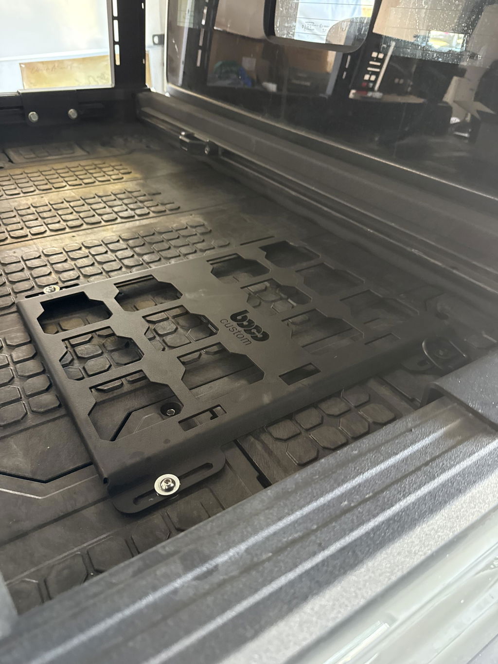
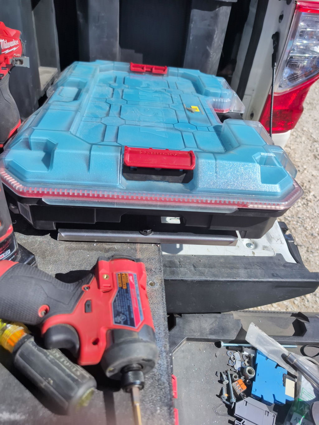
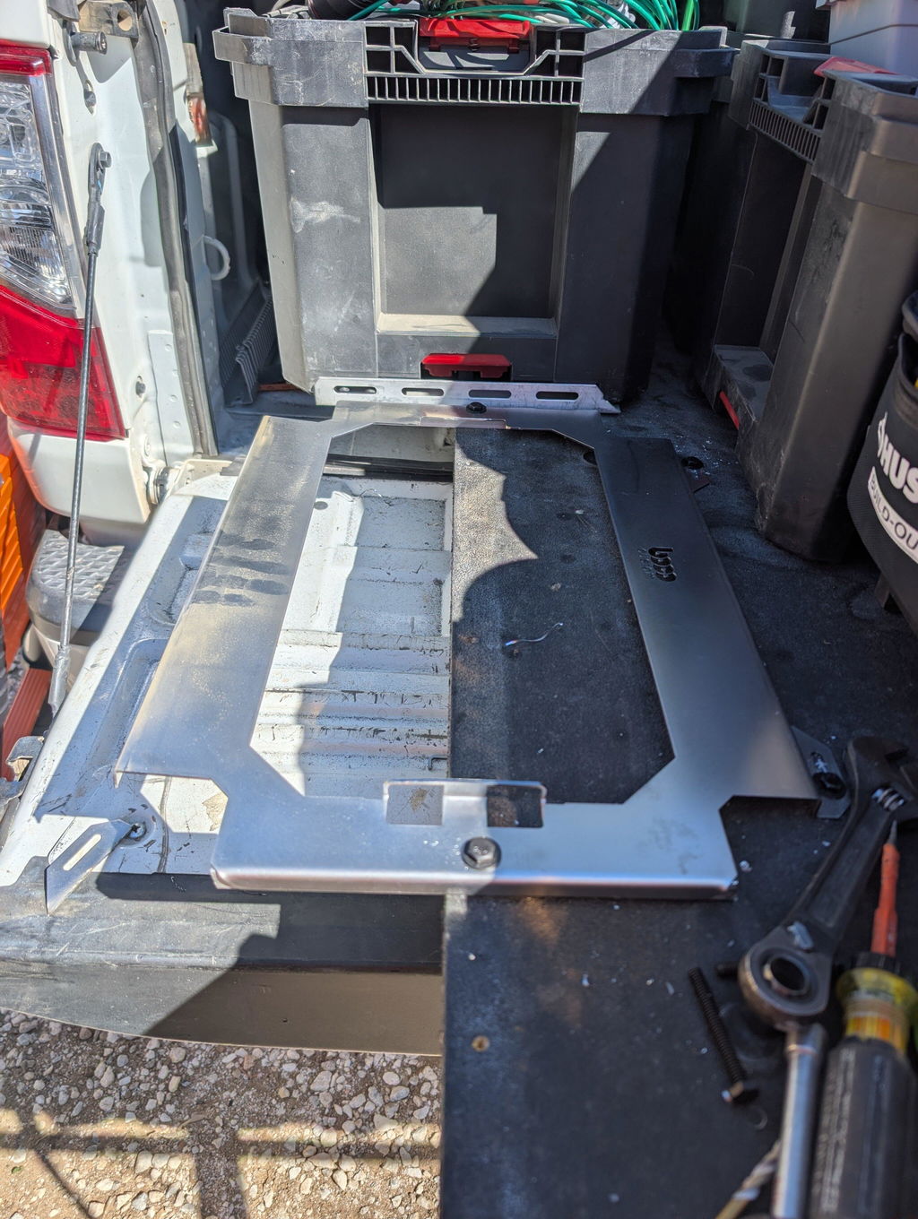
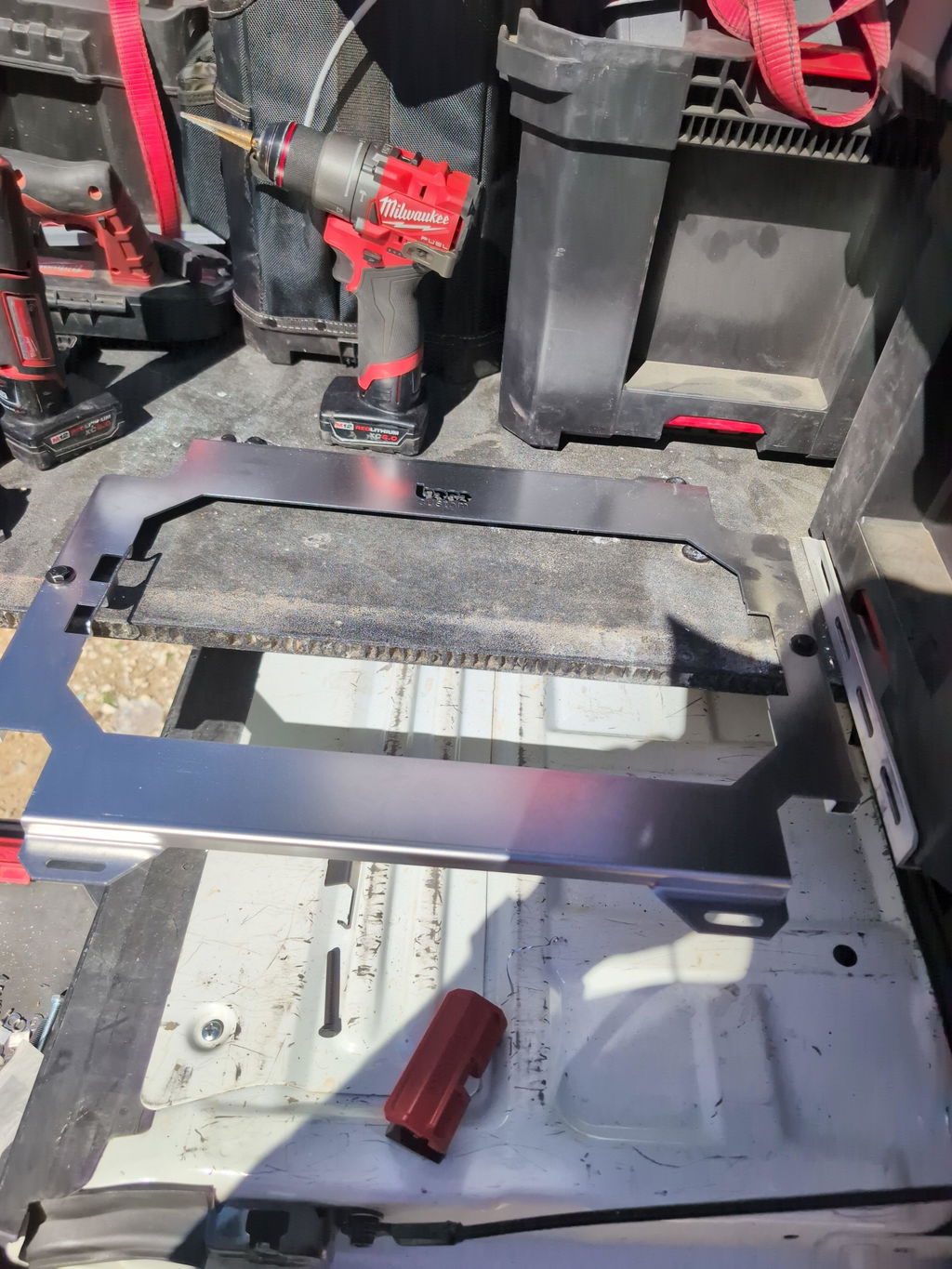
Not only is this way overbuilt for the price with its solid, confident craftsmanship, I am completely convinced that these guys are the best around when it comes to the packout platform.
I like these, they are much more compact than what Milwaukee offers. I had them powder coated in silver vain and they look awesome. I love the bonus half rack they sent me. That’s the mark of a nice company.


Dejar un comentario